
Abstract
A leak test performed according to ASTM F2338-09 Standard Test Method for Nondestructive Detection of Leaks in Packages by Vacuum Decay Method was developed and validated for container-closure integrity verification of a lyophilized product in a parenteral vial package system. This nondestructive leak test method is intended for use in manufacturing as an in-process package integrity check, and for testing product stored on stability in lieu of sterility tests. Method development and optimization challenge studies incorporated artificially defective packages representing a range of glass vial wall and sealing surface defects, as well as various elastomeric stopper defects. Method validation required 3 days of random-order replicate testing of a test sample population of negative-control, no-defect packages and positive-control, with-defect packages. Positive-control packages were prepared using vials each with a single hole laser-drilled through the glass vial wall. Hole creation and hole size certification was performed by Lenox Laser. Validation study results successfully demonstrated the vacuum decay leak test method's ability to accurately and reliably detect those packages with laser-drilled holes greater than or equal to approximately 5 μm in nominal diameter. All development and validation studies were performed at Whitehouse Analytical Laboratories in Whitehouse, NJ, under the direction of consultant Dana Guazzo of RxPax, LLC, using a VeriPac 455 Micro Leak Test System by Packaging Technologies & Inspection (Tuckahoe, NY). Bristol Myers Squibb (New Brunswick, NJ) fully subsidized all work.
LAY ABSTRACT: A leak test performed according to ASTM F2338-09 Standard Test Method for Nondestructive Detection of Leaks in Packages by Vacuum Decay Method was developed and validated to detect defects in stoppered vial packages containing lyophilized product for injection. This nondestructive leak test method is intended for use in manufacturing as an in-process package integrity check, and for testing product stored on stability in lieu of sterility tests. Test method validation study results proved the method capable of detecting holes laser-drilled through the glass vial wall greater than or equal to 5 μm in nominal diameter. Total test time is less than 1 min per package. All method development and validation studies were performed at Whitehouse Analytical Laboratories in Whitehouse, NJ, under the direction of consultant Dana Guazzo of RxPax, LLC, using a VeriPac 455 Micro Leak Test System by Packaging Technologies & Inspection (Tuckahoe, NY). Bristol Myers Squibb (New Brunswick, NJ) fully subsidized all work.
- ASTM F2338
- Container closure
- Container-closure integrity
- Defects
- Glass vial
- Glass vial defects
- Leak
- Leakage
- Leak detection
- Leak test method
- Lyophilized product
- Package
- Package defects
- Package integrity
- Package integrity method
- Vacuum decay
- Vacuum decay leak detection
- VeriPac
Introduction
Parenteral product packaging must be able to prevent product loss due to leakage and to avert ingress of environmental contaminants such as microorganisms, debris, or reactive gases. Stability studies to support new product market approval applications or to assure marketed product quality are required to include tests proving container closure integrity (1). The U.S. Food and Drug Administration has encouraged the use of validated physicochemical leak test methods in lieu of product sterility tests for verifying container closure integrity as a component of product stability studies (2). Integrity tests are also an important component of packaging line qualification studies and as in-process checks of routine manufacturing operations.
The current research describes the development, optimization, and validation of a container-closure integrity test intended for a lyophilized dosage form contained in a parenteral vial package system. The method chosen follows ASTM F2338-09 Standard Test Method for Nondestructive Detection of Leaks in Packages by Vacuum Decay Method (3). This approach is nondestructive, simple to perform, and appropriate for packages of lyophilized dosage forms not requiring a headspace of vacuum or nonreactive gases. ASTM method precision and bias (P&B) studies support the sensitivity and reliability of this approach for parenteral product packages (3, 4). Leak detection results reported in the ASTM P&B work demonstrate this method's ability to detect leaks as small as approximately 5μm in nominal diameter in rigid, nonporous packages. Published studies have shown optimized vacuum decay methods to be more sensitive and reliable than compendial and ISO standard dye ingress tests (5).
Prior to each day of testing, the suitability of the vacuum decay leak test system was confirmed by introducing a controlled leak into the test system via a National Institute of Standards and Technology (NIST)-certified air flowmeter while conducting leak tests using no-defect master packages. The consistent, controlled airflow challenge will yield repeatable and reliable test results given an integral leak test system. These system suitability checks used a test method with pass/fail criteria established during instrument performance qualification. This method is not the final optimized test method for the finished product package detailed in the current report.
Development and optimization of the final test method for the finished product package utilized actual package test samples representing no-defect product packages (negative controls) as well as packages with artificially created defects (positive controls). By testing a population of negative-control, no-defect packages, final method parameters and acceptance criteria took into account virtual leakage derived from outgassing of moisture or other volatiles from package components and/or release of air trapped under the aluminum cap. Positive control packages representing a variety of possible defect scenarios were included in method development and optimization to fully challenge the method in regard to sensitivity and reliability. For instance, leaks located below the product fill level might clog the flow of leaking gas, preventing their detection; therefore, this study used product-filled, with-defect packages to evaluate this possibility. Large leaks might prove hard to detect, as the package headspace gas may be lost during a lengthy test system evacuation, prior to test start. For this reason, larger defect sizes were included, and with-defect packages were filled with glass beads to simulate typical product headspace volumes. Leaks at the stopper-vial interface under the cap might require a longer test time to allow leaking gas to escape from the package. Therefore, positive controls included packages with channels cut across the glass vial finish and with various stopper defects. Finally, vials with holes laser-drilled through the wall simulating cracks or chips were also included; each hole was sized for nominal diameter using a positive air flow measurement technique. Holed vials enabled verification of the test method's sensitivity limit.
Once vacuum decay test method parameters were optimized, final method validation entailed testing a sample population of negative-control, no-defect packages and positive-control packages made using vials with laser-drilled holes (size certified). All validation study packages contained lyophilized product. The test sample population was tested in random order over three replicate test days.
All research was financed by Bristol Myers Squibb, Co. (BMS) of New Brunswick, NJ, and was conducted at Whitehouse Analytical Laboratories (WAL) in Whitehouse, NJ, under the direction of Dana M. Guazzo of RxPax, LLC.
A glossary of terms is provided at the conclusion of this report.
Materials and Methods
1. Test System
All vacuum decay leak tests employed a VeriPac 455 Micro Leak Test System by Packaging Technologies & Inspection (PTI) of Tuckahoe, NY. The VeriPac 455 system is a non-destructive benchtop leak tester. The system consists of a 1000 Torr absolute pressure transducer (measurements in mbar units) plus a 10 Torr differential transducer (measurements in Pa units), an external vacuum pump, and an external test chamber specifically designed for the container to be tested. The design of the leak test system, including the test chamber, ensures minimal deadspace volume, so the smallest leaks will trigger maximal pressure rise readings. (Test chambers designed to closely fit the given test package system are required to ensure maximum test method sensitivity.) A microcalibrator by Furness Controls, Ltd. (Indian Trail, NC) with an operational range of 0.001 to 2.000 cm3 · min−1 (±0.001 cm3 · min−1) was used to introduce a controlled leak into the system as part of suitability tests performed prior to each day of operation, and to challenge the leak test system during method development. Photographs of the test system and the microcalibrator flowmeter are shown in Figures 1A and 1B, respectively. A test system functional diagram is included in Figure 1C.

A. PTI VeriPac 455 Micro Leak Test System. B. Microcalibrator airflow meter. C. PTI VeriPac 455 Micro Leak Test System functional diagram.
2. Test Method Overview
The test is performed by first placing a test package inside the test chamber. The test chamber is closed and the operator activates the test sequence. The test sequence consists of three sequentially programmed time segments discussed below. The length of each time segment is developed specifically for each product-package combination. Two programmed pressure reference limits, also described below, define each test as either pass (no leak) or fail (leak). These limits are also distinct for each product-package system.
2.1. Evacuation Time (Seconds):
Prior to test start, an external vacuum source maintains the VeriPac 455 test system under constant vacuum while a closed valve separates the test chamber from the evacuated test system (Maintaining the system under a vacuum between tests provides more consistent, reliable test results by preventing the accumulation of volatiles in the test system, stabilizing the absolute pressure transducer, and shortening the evacuation time segment.) Upon test sequence activation, this valve opens allowing the rapid establishment of a vacuum in the test chamber. When the evacuation time is complete, a second valve closes, isolating the vacuum source from the fully evacuated test system plus test chamber. The absolute pressure transducer measures pressure in the test system plus test chamber (system/chamber) throughout evacuation.
2.2. Equalization Time (Seconds):
An equalization time segment immediately follows evacuation. This time segment allows for system/chamber pressure equilibration (stabilization). The absolute pressure transducer monitors system/chamber pressure throughout equalization.
2.3. Test Time (Seconds):
A test time segment follows equalization while the absolute pressure transducer continues to monitor the pressure rise in the system/chamber. The differential pressure transducer simultaneously tracks the net rise in pressure within the system/chamber from the beginning to end of the test time. At the completion of this last time segment, the system/chamber vents allowing test package removal from the test chamber. Immediately post-venting, the valve separating the test system from the test chamber closes, the valve between the vacuum source and the test system opens, and the test system returns to its pre-test evacuated state. The test result is reported as either pass or fail in accordance with the established pressure reference limits. In addition, the final pressure readings from the absolute and differential pressure transducers are displayed and recorded.
2.4. Pressure Reference Limits:
Tests pass or fail according to two pressure reference limits unique to each product-package combination. For a test sample to pass (i.e., to show no leakage), test results must comply with both pressure reference limit specifications. A test will fail (i.e., show leakage) if either pressure reference limit specification is not met.
2.4.1. Absolute Pressure Reference Limit (mbar)The test will pass if the absolute pressure transducer reading monitored from equalization start to the end of the test is less than the absolute pressure reference limit (APRL). The test will fail (and the cycle will abort) if the absolute pressure is equal to or greater than the APRL.
The test will pass if the differential pressure transducer reading monitored throughout the test time segment remains less than the differential pressure reference limit (DPRL). The test will fail (and the cycle will abort) if the differential pressure is equal to or greater than the DPRL.
2.5. System Flush:
The vacuum decay leak test instrument/chamber itself must be relatively free of virtual and real leaks in order to detect the smallest leakage from test packages. To prevent the accumulation of volatiles in the test system that might yield a virtual leak pressure rise, the test system is programmed to maintain vacuum conditions between tests, as previously noted in Section 2.1. Test chamber sealing surfaces are cleaned periodically to prevent debris build-up on test chamber sealing surfaces that could cause background leakage. Cleaning is performed by wiping surfaces with a low-lint wipe moistened with distilled or purified water. After cleaning, the chamber is closed and the test system/chamber is flushed (i.e., evacuated) in order to dry gasket surfaces. A 60 s flush time was selected for this study.
3. Test Sample Population
3.1. Product-Package System:
The lyophilized product was packaged in a 20 mL capacity glass vial of Type I tubing with a 20 mm finish diameter. Each vial was stoppered using a 20 mm lyophilization-style stopper, and was closed with an aluminum crimp cap with a plastic flip top. The headspace in each product-filled package consisted of air at ambient pressure.
3.2. Test Packages:
Test packages included master packages guaranteed free of leaks, negative-control test packages with no known defect, and positive-control packages with known package defects, all briefly described below. Test packages specified for test system suitability, method development, and method validation are identified in Table I. Test package and component illustrations are included in Figures 2⇓⇓⇓⇓⇓⇓⇓⇓⇓–12.
3.2.1. Master packages (test sample ID codes 5-1 to 5-5), guaranteed leak-free, were filled to overflow capacity with silicone sealant, stoppered, and capped. Master packages were used for system suitability tests and as part of method development and method validation. (Note: Masters made of other materials were explored but were rejected. Vacuum decay results of masters made of the same vial/stopper/cap components as actual product packages more closely mirrored results of actual product-filled, no-leak packages.)
3.2.2. Negative-control packages for method development included empty vials, stoppered and capped at WAL (test sample ID codes 2-1 to 2-10), and product-filled vial packages assembled by BMS (test sample ID codes 13-1 to 13-10). Negative-control packages used for method validation were all product-filled and assembled by BMS (test sample ID codes N-1 to N-70).
3.2.3. Positive-control packages with defective stoppers (test sample ID codes S-1, S-6, and S-7) used during method development were filled with glass beads to simulate normal product fill level. Defective stoppers were either pierced using a needle or cut with scissors. These packages were prepared by WAL.
3.2.4. Positive control packages used for method development included a variety of vial defect types, all prepared by WAL. First, vials with channels cut across the finish area and filled with glass beads were used (test sample ID codes V-1 to V-11). Second, vials with laser-drilled holes in the vial neck, filled with glass beads, were stoppered so that the hole was either blocked by the inserted lyophilization stopper leg (test sample ID codes 27-1-X to 27-15-X) or was between the stopper legs and therefore unblocked (test sample ID codes 27-1-O to 27-15-O). Method validation positive control packages having vial defects only included vials with laser-drilled holes, hand-filled with lyo-powder, stoppered, and capped (test sample ID codes P-1 to P-30). All laser-drilled holes were created by Lenox Laser of Glen Arm, MD. Hole target sizes were approximately 3 μm, 5 μm, and 15 μm in nominal diameter. Lenox Laser certified the size of each manufactured hole to within an uncertainty of ±2.5%, with an orifice size tolerance of ±10%.
Test Sample Identification

Master test package.

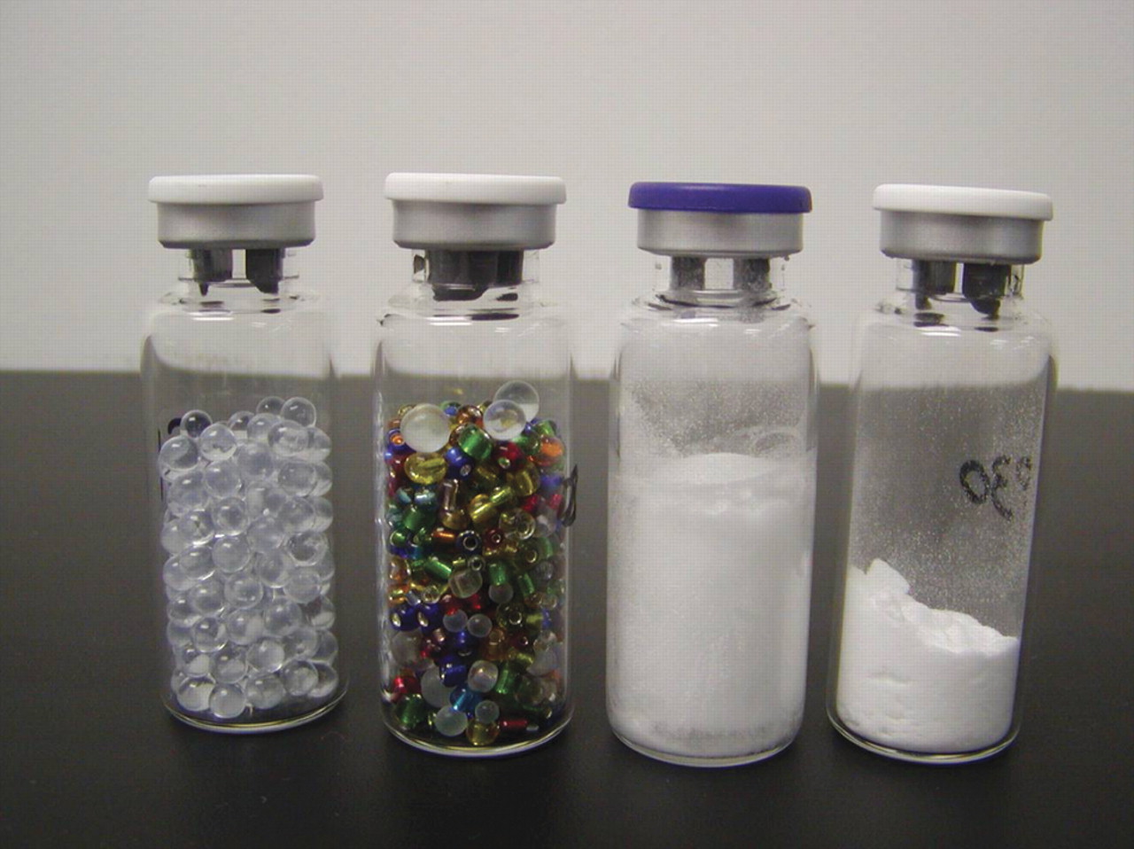
Test package components: glass vial, elastomeric stoppers, aluminum caps with plastic flip tops.

Package fill variations. Left to right: Glass-bead-filled packages (2), lyophilized product-filled package supplied by BMS, lyophilized product manually transferred from original vial to with-hole vial (used in method validation).

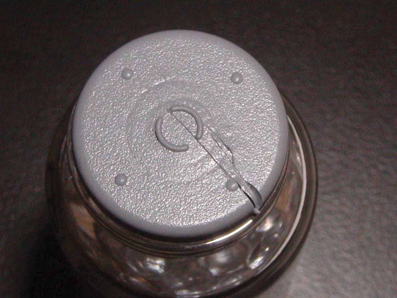
Closure defect S-1. Single 21 gauge needle puncture. Bottom figure: 25× (Magellan V200 Videomicroscope).

Stopper defect S-6. Single radial cut.

Stopper defect S-7. Flange edge removed.

Glass vial defect V-1. Land seal surface channel. 25× (Magellan V200 Videomicroscope).

Glass vial defect V-6. Valve seal surface channel. Top view: 25×; Bottom view: 115× (Magellan V200 Videomicroscope).

Glass vial defect V-9. Land + valve seal surfaces channel. 25× (Magellan V200 Videomicroscope).

Glass vial defect V-10. Land + valve seal surfaces channel. 25× (Magellan V200 Videomicroscope).

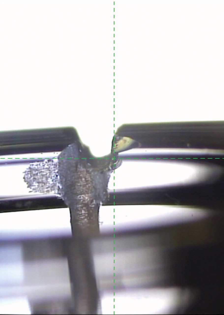
Laser-drilled hole in vial neck. Top image, left to right: Vial 27-3—Hole in “O” closure position, Hole in “X” closure position. Bottom image: 2.93 μm nominal hole diameter, by Lenox Laser, of Glen Arm, MD. 25X (Magellan V200 Videomicroscope).
4. Test Parameter Selection Procedure
The vacuum decay leak test for each product-package system is defined by a unique combination of time and pressure parameter limits (refer to Materials and Methods, Section 2). Accurate and repeatable identification of with-leak and without-leak packages requires appropriate selection of evacuation, equalization, and test time limits, as well as pressure limits, APRL and DPRL. These parameter limits are determined by performing a series of method development and optimization experiments.
Evacuation time should be just long enough to establish consistent system/chamber target pressure readings for no-leak packages. (The VeriPac test system employed during this study used a target pressure of about 0.1 mbar.) Conversely, evacuation times that are too long will remove essentially all headspace gas from largely leaking packages; without headspace gas, no pressure rise will occur and the leak will go undetected. Equalization time should be long enough to allow the system to stabilize, yielding consistent absolute pressure readings for no-leak packages. Test time should be long enough for packages with the smallest leaks to yield significantly greater pressure readings (in mbar and/or Pa units) than no-leak packages. Absolute and differential pressure reference limits are established by observing the pressure rise in the system/chamber for no-leak packages versus known-leaking packages when tested according to the proposed time segment limits (prior to final pressure reference limits selection, programmed pressure limit values should be quite high to prevent test cycle abortion). The final time segment lengths and pressure reference limits chosen should permit no-leak packages to pass, while detecting with-leak packages.
The current study considered package-to-package and day-to-day differences when selecting time and pressure limits. Varying time gaps between tests were also explored. ASTM F2338-09 P&B studies (3) also investigated variability among instruments and test sites. In the present study, research was limited to one instrument/test chamber and one test site.
5. Package Leak Test Method Validation
After method optimization and pressure limit acceptance criteria were defined, a validation study was performed to demonstrate the detection limit of the final vacuum decay leak test method for testing BMS product-filled packages with and without laser-drilled hole defects, using the PTI VeriPac 455 Micro Leak Test System. A random-order test sample population of 70 negative-control, no-defect packages and 30 positive-control, with-defect packages were tested in replicate over 3 days. Method validation acceptance criteria required all negative-control packages to pass (no leak detected), and all positive-control packages made with laser-drilled holes in the vial neck 5 μm and larger in nominal diameter to fail (leak detected).
Results and Discussion
1. System Suitability Tests
Suitability tests were performed each day of operation to verify the VeriPac 455 test system's functionality and to confirm the absence of system/chamber leaks. System suitability checks used a test method with pass/fail criteria established during instrument performance qualification. This method is not the final optimized test method for the finished product package detailed in the current report. Test acceptance criteria for system suitability were
All 10 leak tests of master packages must be passed.
All five leak tests of master packages with a NIST airflow challenge of 0.100 ± 0.005 (cm3 · min−1) introduced into the test system must show failure.
The time parameter limits for system suitability tests were established using a set of five master packages and 10 negative-control, product-filled packages to represent no-leak tests, and using the NIST microcalibrator airflow meter to introduce a controlled leak into the test system. The test parameter selection procedure outlined in Materials and Methods, Section 4, was followed. The absolute and differential pressure reference limits were set based on data from no-leak mean absolute and differential pressure readings measured over multiple days of testing. Table II outlines the parameter limits of the final system suitability test method. All current study system suitability tests performed met the acceptance criteria, namely, all master tests passed and all with-leak tests (0.100 cm3 · min−1) failed.
System Suitability Test Method Parameter Settings
2. Package Leak Test Method Development
The final package integrity test method was required to meet the following acceptance criteria.
All packages with no known defect must pass (i.e., no leakage detected).
All packages with a hole in the vial of greater than or equal to 5 μm in nominal diameter must fail (i.e., leakage detected).
Method time and pressure parameter limits were optimized according to the test parameter selection procedure presented in Materials and Methods, Section 4, and described in detail in the following sections. Packages used for this work included master packages and negative-control packages filled with lyophilized product. Positive-control packages were used to investigate the method's ability to find various defect types. Positive-control packages included vials with laser-drilled holes, vials with channel defects cut across finish surfaces, and artificially defective closures (refer to Table I for a list of negative and positive controls).
2.1. Evacuation Time Optimization:
Negative-control, product-filled packages supplied by BMS (13-1 to 13-10) were exposed to evacuation times ranging from 3 to 7 s (Tables IIIa, IIIb). An evacuation time of 6 s was sufficiently long to ensure consistent 0.1 mbar absolute pressure readings at the end of evacuation time for all negative-control packages tested. Positive-control packages with vial channel defects (V-1 to V-11) were then tested with an evacuation time of 6 s (Table IIIc). Two vials with land surface channel defects (V-2, V-4) and all vials with channels cut across both valve and land seal surfaces (V-9 to V-11) gave absolute pressure readings much greater than those of the no-defect vials. Therefore, with appropriate APRL settings, packages with such large defects should be detectable following a 6 s evacuation time. The other vials with either land channels or valve channels (V-1, V-3, V-5 to V-8) exhibited absolute pressure readings matching the negative control packages (0.1 mbar) after 6 s evacuation; these vials either leaked more slowly or the closures effectively sealed the channel paths. During all evacuation optimization tests the system suitability test method APRL of 2.7 mbar was used; the DPRL was irrelevant, as tests did not proceed beyond initial evacuation.
Test Method Evacuation Time Optimization IIIa. Test Parameter Settings
Negative-Control Tests
Positive-Control Tests
2.2. Equalization Time Optimization:
Negative-control, product-filled BMS packages (13-1 to 13-10) were tested both with and without the addition of a NIST airflow artificial leak (0.100 cm3 · min−1), using a 6 s evacuation period, followed by variable equalization times (Tables IVa, IVb). A 20 s equalization time produced consistent absolute pressure readings for negative-control packages. During the equalization time segment, noticeable differences could be observed between no-leak-added and with-leak-added pressure readings.
Test Method Equalization Time Optimization, 0–20 s IVa. Test Parameter Settings
Negative Control Tests, with and without NIST Airflow Leak
Master, Negative, and Positive Control Tests
Masters and negative-control and positive-control packages were subsequently tested using a 20 s equalization time segment, preceded by either 6 s or 7 s evacuation (Table IVc). Tests using 6 s evacuation yielded pressure readings 10 fold greater for bigger channel defect packages (V-2, V-4, V-9, V-10, V-11), and for packages with larger 12 to 14 μm holes (27-6-O to 27-10-O), as compared to no-defect packages (masters, negative controls). Some smaller channel defect packages (V-5 to V-8) and vials with holes about 5 μm in nominal diameter (27-11-O to 27-15-O) demonstrated absolute pressure readings about 2 or 3 fold greater than no-defect packages. There was no difference in pressure readings between negative-control packages and packages with holes smaller than 5 μm. Increasing evacuation time to 7 s lowered absolute pressure readings for several of the known-leaking packages tested, likely due to more package headspace gas loss from these larger leak packages during test cycle evacuation (Table IVc). Therefore, a 6 s evacuation time rather than 7 s, coupled with 20 s for equalization, was preferred to ensure detection of the largest package leaks.
Extending equalization time from 20 s to 60 s was attempted to see if very long equalization may produce lower, more consistent test time differential pressure readings for negative-control packages, making it possible to detect the smallest vial-hole leaks during the final test time segment (Table V). A 20 s test time segment and a DPRL of 100 Pa was chosen for these tests (Table Va). Positive controls included packages having 2.4 to 3.4 μm holes blocked by the closure leg (27-1-X to 27-5-X). A 60 s equalization time did result in lower differential pressure readings, but no significant difference in differential pressures was observed between negative controls and the smallest-hole packages (Table Vb). Therefore, lengthening equalization beyond 20 s proved unbeneficial.
Test Method Equalization Time Optimization, 20 s versus 60 s Va. Test Parameter Settings
Negative and Positive Control Tests
2.3. Test Time Optimization:
Test time optimization trials included test time segments of 10 s, 20 s, and 30 s (evacuation and equalization times were kept constant at 6 s and 20 s, respectively) (Table VI). Absolute and differential pressure reference limits were set high (50 mbar and 100 Pa) to prevent premature test cycle abortion.
Test Method Test Time Optimization VIa. Test Parameter Settings
As summarized in Table VIb, the shortest 10 s time segment easily permitted reliable detection of vial holes greater than or equal to about 5 μm, producing absolute and differential pressure readings well above master or no-defect packages. Lengthening the test time to 20 s or 30 s made it possible to reliably detect vials with holes of about 3 μm, as differential pressure readings of with-hole packages were as much as 2 fold those of nonleaking packages. Upright and inverted packages tested for 30 s demonstrated no difference in results, implying that powdered product, simulated by glass beads, would have no impact on test results (the hole in test package 27-2-O appears to have clogged; results duplicate no-defect packages for all tests attempted).
Master, Negative and Positive Control Packages Tests
A microcalibrator was used to introduce a NIST traceable airflow leak into the test system/chamber during negative-control package leak tests to evaluate a 30 s test time leak test method (with 6 s evacuation and 20 s equalization, Table VII). Absolute and differential pressure reference limits were set high (50 mbar and 100 Pa) to avert test cycle abortion. Tests with a 0.050 cm3 · min−1 microcalibrator leak yielded similar results to packages with holes about 3 μm in nominal diameter, with pressure readings about twice those of negative-control packages (refer to Table VIb, 30 s tests). With-leak data on day 1 versus day 2 were essentially identical. Thus a test time of 30 s supports the required leak size detection limit of 5 μm and larger with a comfortable safety margin.
Test Method Sensitivity Verification Using NIST Airflow Leaks VIIa. Test Parameter Settings
Negative Control Tests, with and without NIST Airflow Leaks
2.4. Test Method Repeatability, and Proposed APRL and DPRL Determination:
The proposed leak test method—6 s evacuation, 20 s equalization and 30 s test—was used to perform 3 day replicate tests of a random order population set of positive- and negative-control packages in order to verify the method's day-to-day repeatability. For these tests, the absolute and differential pressure reference limits were set intentionally high at the time of testing in order to prevent test cycle abortion, enabling end-of-test pressure readings for all but the largest leaks (APRL = 50 mbar, DPRL = 100 Pa). Absolute and differential pressure readings were necessary so that appropriate APRL and DPRL values could be calculated for the final test method, taking into account normal day-to-day and sample-to-sample pressure reading variations.
The test sample population included 40 negative-control packages, five negative-control packages with NIST airflow leak added, and 24 positive-control, with-defect packages. Thirty negative-control packages included BMS-manufactured product packages and 10 WAL hand-assembled empty packages. Positive-control packages included vials with laser-drilled holes ranging in size from 2.39 to 14.14 μm, all with stoppers positioned so that the inserted stopper leg blocked the vial neck hole. Other positive controls included stoppers with a single needle puncture (S-1), a radius cut (S-6), and a missing flange edge (S-7). Vials with channel defects included those with a channel at the land surface only (V-2, V-4), with a channel along the valve or neck only (V-6 to V-8), and with a channel along both valve and land surfaces (V-9 to V-11).
Test results from the no-defect packages tested according to the parameter settings listed in Table VIIIa are summarized in Table VIIIb. Final test method APRL and DPRL were calculated by adding six standard deviations to the no-defect package absolute and differential pressure reading means, respectively. The calculated final APRL was 3.7 mbar, and the DPRL was 67 Pa. With these limits as leak test pass/fail criteria, the 3 day replicate test results were re-examined, and the following observations summarized in Table VIIIc were made.
Proposed Final Method Repeatability Tests VIIIa. Test Parameter Settings
Negative-Control Packages1 Statistical Analysis
Positive and Negative Control Tests Summary
• Packages that failed (i.e., leakage was detected) included
∘ all packages with vial laser-drilled holes greater than or equal to 3.38 μm in nominal diameter
∘ all negative control packages with a NIST 0.050 cm3 · min−1airflow leak
∘ all packages with vial land seal surface channels only (V-2, V-4)
∘ all packages with vial land plus valve seal surface channels (V-10, V-11)
• Packages that passed (i.e., no leakage detected) included
∘ all negative-control, no-leak packages
∘ all packages with vial laser-drilled holes less than 3.38 μm in nominal diameter
∘ all stopper defect packages (S-1, S-6, S-7)
∘ all packages with vial valve land seal channels only (V-6, V-7, V-8)
Based on these results, the final test method with proposed pressure reference limits met the required package integrity leak test acceptance criteria. Namely, all packages with no known defect passed, and all packages with a hole in the vial greater than or equal to 5 μm in nominal diameter failed. The additional positive control tests demonstrated the method's ability to detect various defect types and sizes. For instance, the method detected an air leak of 0.050 cm3 · min−1 introduced into the test system/chamber. The method detected vial hole defects as small as 3.38 μm in nominal diameter. The four hole defects missed were 2.39–2.93 μm in diameter, with differential pressure measurements of 54–61 Pa, closely approaching the 67 Pa DPRL limit. The method also found vial channel defects that permit package headspace gas leakage at the stopper/vial land seal surface interface. Vial neck defects not affecting the land sealing surface did not cause package leakage. Stopper defects not detected included a single 21-gauge needle puncture, a single radius cut, and a missing closure flange edge. The method was unable to identify these defects likely due to the viscoelastic nature of the closure formulation making it possible for the closure to re-close when punctured or cleanly cut, and to conform to vial surfaces when compressed and capped into place. The inability to find certain stopper defects by vacuum decay, and the lack of leakage from vials having only neck defects, both illustrate the point that no leak test method exists that can prevent or detect all package defect types. Other means are necessary to preclude defects such as these from the package assembly line.
3. Package Leak Test Method Validation
3.1. Purpose:
A validation study was performed to demonstrate the detection limit of the final vacuum decay leak test method for testing BMS product-filled packages with and without laser-drilled hole defects, using the PTI VeriPac 455 Micro Leak Test System.
3.2. Test System Suitability:
Prior to each test day, the VeriPac 455 test system was shown suitable for use by successfully meeting the system suitability criteria (refer to Table II for system suitability test method parameters). Specifically, five master packages were leak-tested using a test cycle consisting of 6 s evacuation, 20 s equalization, and 10 s test, with APRL and DPRL of 2.7 mbar and 30 Pa, respectively. Each master package was tested once with the NIST-traceable microcalibrator closed (no leak). Then each master was tested again with the microcalibrator open to introduce an airflow rate of 0.100 cm3 · min−1 into the test system/chamber. Finally, each master was tested again with the microcalibrator closed. The test system was suitable for use if all 10 tests with microcalibrator closed passed (no leak detected), and all five tests with microcalibrator open failed (leak detected).
3.3. Validation Protocol:
The optimized leak test method was used to test a random-order test sample population of negative- and positive-control packages on each of three replicate test days. The final method consisted of 6 s evacuation, 20 s equalization, and 30 s test time, with an APRL and DPRL of 3.7 mbar and 67 Pa, respectively. The refrigerated test samples were tested after coming to ambient room temperature to avoid false-positive results caused by package surface condensation.
Test samples included 70 negative-control, no-defect lyophilized product packages, filled and assembled by BMS. Test samples also included 30 positive-control, with-defect packages prepared at WAL by transferring lyophilized product from BMS-supplied packages to vials with a single laser-drilled hole in the vial neck, hand-stoppered and capped using a hand-crimping tool. Three groups of 10 holed vials were included, representing nominal hole diameters of about 3 μm (range, 2.39–3.17 μm), 5 μm (range, 4.36–6.02 μm), and 15 μm (range, 12.08–15.04 μm). Validation study test samples are listed in Table I.
To avoid risk of false-positive results due to test chamber gasket debris, test chamber sealing surfaces were wiped clean followed by a 60 s system flush at regular intervals throughout validation. Nevertheless, the protocol included the following procedure to address possible false-positive test results.
If a test package result was questionable (e.g., a no-defect package fails), the test package was removed from the test chamber, the chamber sealing surfaces were cleaned, and a 60 s system flush was performed. A master was tested. Once the master test passed, confirming test system performance and test chamber integrity, the questionable package was retested.
If the test package retest result was pass, then the initial result was considered invalid due to debris on the test chamber sealing surfaces or operator error (e.g., the test chamber was improperly closed). The repeat test result was the final result. The test package passed.
If the test package retest result showed failure, both the original and the repeat tests were considered final. The test package failed.
3.4. Acceptance Criteria:
The following acceptance criteria were applied to test results on each day of validation.
All 70 negative-control packages must pass.
All 10 positive-control packages with holes approximately 5 μm in nominal diameter must fail.
All 10 positive-control packages with holes approximately 15 μm in nominal diameter must fail.
Test results obtained with the 10 positive-control packages with holes approximately 3 μm in nominal diameter were included in the validation study for information only.
3.5. Results:
3.5.1. Test System Suitability TestsTest system suitability criteria were successfully met each day of validation. All 10 tests with microcalibrator closed passed (no leak detected), and all five tests with microcalibrator open to deliver a 0.100 cm3 · min−1 leak failed (leak detected).
Test method results are summarized in Table IX. In short, test method validation criteria were successfully met on each of day of validation. All 70 negative control packages (N-1 to N-70) passed (leak detected). All 10 positive control packages with holes approximately 5 μm in nominal diameter (P-11 to P-20) failed (leak detected). All 10 positive-control packages with holes approximately 15 μm in nominal diameter (P-21 to P-30) also failed. The 10 positive-control packages with holes approximately 3 μm in nominal diameter (P-1 to P-10) were included in the validation study for information only. Three of 10 packages in this hole size group failed (were detected), seven of 10 passed (were not detected). Interestingly, each of the three holes detected on all three days were 3.17 μm in nominal diameter (P-2, P-9, P-10). The remaining undetected holes were smaller, ranging in size from 2.39 to 2.67 μm in nominal diameter. Creating and sizing such tiny holes is challenging. These holes are prone to clogging with environmental debris, making their viability questionable. In addition, variability in pressure rise readings observed with negative control packages, combined with test system degassing, make reliable detection of the minuscule pressure rise from leaks much smaller than 5 μm difficult.
Final Method Validation Tests IXa. Test Parameter Settings
Positive and Negative Control Tests Summary
Conclusion
A vacuum decay leak test method was successfully developed and validated for nondestructive container closure integrity testing a BMS lyophilized product packaged in a glass vial, stoppered, and closed with an aluminum seal. This nondestructive leak test method is intended for use in manufacturing as an in-process package integrity check, and for testing product stored on stability in lieu of sterility tests.
The method is performed according to ASTM F2338-09 Standard Test Method for Nondestructive Detection of Leaks in Packages by Vacuum Decay Method. The instrument used for all work was the PTI VeriPac 455 Micro Leak Test System. The time required for performing the test is less than 1 min per package. The leak test method was evaluated for detection limit as defined by USP General Chapter 〈1225〉 Validation of Compendial Procedures. The detection limit of the VeriPac 455 leak test method was proven greater than or equal to 5 μm in nominal hole size. Development studies investigated the ability of the method to detect other package defect types, including vial channel defects and stopper defects.
Glossary of Terms
Absolute pressure. Pressure measurement expressed in true, or absolute, pressure units.
Absolute pressure reference limit (mbar). The vacuum decay leak test pass/fail limit determined by an absolute pressure transducer.
Absolute pressure transducer. A tool that provides a measure of “true” pressure above absolute zero pressure. For example, the absolute pressure transducer in the VeriPac 455 measures the absolute pressure in the test system throughout the test cycle in mbar units.
Differential pressure. Pressure measurement expressed as pressure units greater or lesser than a given reference pressure.
Differential pressure reference limit (Pa). The vacuum decay leak test pass/fail limit determined by a differential pressure transducer.
Differential pressure transducer. A tool that provides a measure of pressure above or below the chosen reference pressure. For example, the differential pressure transducer in the VeriPac 455 measures the differential pressure (i.e., pressure change) starting from equalization time end (reference pressure = 0 Pa), to test time end, in Pa units.
Leak. A gap or defect in the package wall capable of permitting gas mass flow into or out of the package. Leaks are rarely, if ever, precise holes or channels of defined dimension; therefore, leak size is typically expressed in leakage rate units. The nominal hole size dimensions of the glass vial laser-drilled hole defects cited in the report were determined using flow meters with a laser-drilled orifice in a metal plate as calibration standards.
Leakage rate. The rate of fluid flow through a leak path, without regard to the physical size of the hole through which the flow occurs. Fluid denotes any liquid or gas that can flow. Factors that affect leakage rate include the fluid itself, the leak path dimensions, and the pressure difference across the leak path. Gas mass flow leakage rate is expressed in SI units of Pascal cubic meters per second (Pa · m3 · s−1). The current study reports air flow measured in units of cubic centimeters per minute (cm3 · min−1), taken at ambient (not standard) temperature and pressure conditions.
Pressure measurement terms. One standard atmosphere (atm) pressure is equivalent to 760 Torr, 1.01325 × 10⁵ Pascal (Pa), or 1000 mbar.
Vial finish. The top of a vial consisting of the vial mouth opening and the flange lip.
Vial flange. The lip of the vial extending around the vial mouth. An aluminum cap is sealed onto a vial by tucking the cap skirt under the vial flange.
Vial land seal channel. A channel extending horizontally across the land seal surface from the vial mouth opening to the outer finish edge.
Vial land seal surface. The horizontal surface on top of a vial. An elastomeric closure sufficiently compressed onto the top of a vial effects a seal across the land seal surface.
Vial valve seal channel. A channel extending vertically from the vial mouth opening into the vial neck.
Vial valve seal surface. The vertical surface along the inner neck of the vial. The plug of an elastomeric closure may affect a valve seal when the closure is inserted into the vial mouth.
Virtual leak. A virtual leak is caused by the emission of gases and vapors present within the test system that falsely mimics actual leakage. Virtual leaks may result from vapors or gases sorbed into or onto test system surfaces, or trapped between package components.
Conflict of Interest Declaration
Author Heinz Wolf is an employee of Packaging Technologies & Inspection, LLC, the manufacturer of the PTI VeriPac 455 Micro Leak Test System. All other authors declare they have no competing interests.
Acknowledgments
Bristol Myers Squibb staff: Madhav S. Kamat, Research Fellow, Drug Product Science and Technology. Whitehouse Analytical Laboratories staff: Therese Abrenica, Laboratory Manager; Sandra Metroka, Quality Assurance Manager; Eric Creveling, Senior Laboratory Analyst.
- © PDA, Inc. 2011
References


Jump to section
Related Articles
Cited By...
- Method Development for Container Closure Integrity Evaluation via Headspace Gas Ingress by Using Frequency Modulation Spectroscopy
- Feasibility of Using Fluorescence Spectrophotometry to Develop a Sensitive Dye Immersion Method for Container Closure Integrity Testing of Prefilled Syringes
- Integration of Regulatory Guidelines into Protein Drug Product Development