
Abstract
In Part 1 of this three-part research series, a leak test performed using high-voltage leak detection (HVLD) technology, also referred to as an electrical conductivity and capacitance leak test, was developed and validated for container–closure integrity verification of a small-volume laminate plastic bag containing an aqueous solution for injection. The sterile parenteral product is the rapid-acting insulin analogue, insulin aspart (NovoRapid®/NovoLog®, by Novo Nordisk A/S, Bagsværd, Denmark). The aseptically filled and sealed package is designed to preserve product sterility through expiry. Method development and validation work incorporated positive control packages with a single hole laser-drilled through the laminate film of each bag. A unique HVLD method characterized by specific high-voltage and potentiometer set points was established for testing bags positioned in each of three possible orientations as they are conveyed through the instrument's test zone in each of two possible directions—resulting in a total of six different test method options. Validation study results successfully demonstrated the ability of all six methods to accurately and reliably detect those packages with laser-drilled holes from 2.5–11.2 μm in nominal diameter. Part 2 of this series will further explore HVLD test results as a function of package seal and product storage variables. The final Part 3 will report the impact of HVLD exposure on product physico-chemical stability.
LAY ABSTRACT: In this Part 1 of a three-part research series, a leak test method based on electrical conductivity and capacitance, called high voltage leak detection (HVLD), was used to find leaks in small plastic bags filled with an insulin pharmaceutical solution for human injection by Novo Nordisk A/S (Bagsværd, Denmark). To perform the test, the package is electrically grounded while being conveyed past an electrode linked to a high-voltage, low-amperage transformer. The instrument measures the current that passes from the transformer to the electrode, through the packaged product and along the package walls, to the ground. Plastic packages without defect are relatively nonconductive and yield a low voltage reading; a leaking package with electrically conductive solution located in or near the leak triggers a spike in voltage reading. Test methods were optimized and validated, enabling the detection of leaking packages with holes as small as 2.5 μm in diameter. Part 2 of this series will further explore HVLD test results as a function of package seal and product storage variables. The final Part 3 will report the impact of HVLD exposure on product stability.
- Container-closure
- Container-closure integrity
- Defects
- Electrical conductivity and capacitance leak detection
- Form-fill-seal packages
- High-voltage leak detection
- HVLD
- Leak
- Leakage
- Leak detection
- Leak test method
- Package
- Package defects
- Package integrity
- Package integrity method
- Plastic laminate bag
- Protein product
- Stability
- Insulin.
Introduction
Parenteral product–package integrity is critical to protect the package contents from loss or from contamination by microorganisms, environmental debris, or reactive gases. Stability studies to support new product market approval applications or to assure marketed product quality are required to include tests proving container-closure integrity (1). The U.S. Food and Drug Administration has encouraged the use of validated physicochemical leak test methods in lieu of product sterility tests for verifying container–closure integrity as a component of product stability studies (2). Both the regulatory authorities in the United States and the European Union specify that containers closed by fusion, for example glass or plastic ampoules, should be subject to 100% integrity testing prior to marketed product or clinical study distribution (3, 4). The product–package which is the subject of the current study is the rapid-acting insulin analogue, insulin aspart (NovoRapid®/NovoLog®, by Novo Nordisk A/S, Bagsværd, Denmark) packaged in just such an aseptically filled and fusion-sealed laminate plastic bag.
High-voltage leak detection (HVLD), also known as electrical conductivity and capacitance test, was chosen for nondestructive package integrity testing the product–package after exploring a variety of commonly used test methods. Vacuum decay leak detection was first investigated, but was abandoned for several reasons (5). First, the proteinaceous active clogged package leak paths preventing their detection. Second, leakage into the test chamber required test chamber cleaning and drying downtime. Third, the high-vacuum test conditions needed to detect liquid-filled leak paths caused plastic package outgassing that masked the pressure rise from smallest leaks. Last, vacuum decay 30 s test time restricted its use in routine manufacturing to quality control tests of lot statistical samples. By comparison, HVLD is rapid, needing only a few seconds to test each bag; little package contact is required for testing; and line cleanup from leaking packages is much simpler. Therefore, HVLD proved to be the only viable method for identifying leaks in the product-filled bags, and had the added advantage of enabling rapid, in-line, 100% product–package integrity testing. As noted above, integrity testing all manufactured units is required by regulatory agencies for form-fill-seal package systems. HVLD has enjoyed a long history of use as a package leak test method for foods and pharmaceutical products dating back to the 1970s. Möll and colleagues published a study demonstrating the usefulness of HVLD for leak testing form-fill-seal plastic ampoules filled with a sterile pharmaceutical product for topical application (6). Still, research was required to prove the ability of HVLD to detect leaks in the current laminate bag package, including leaks clogged with protein product, and to verify that HVLD exposure does not degrade the product's active ingredient.
Part 1 research describes the development and validation of HVLD test methods used to leak test these product-filled plastic laminate bags. The HVLD unit used was a laboratory-scale Nikka Densok USA, Inc. HDT-1 pinhole inspector (Lakewood, CO) with data acquisition system by TellTech Service Corporation (Mahopac, NY). This small-scale instrument had one test zone, whereas larger, in-line instruments incorporate multiple in-line test zones enabling continuous in-line testing of multiple package surfaces. Due to the complexity of the package design, it is possible to check bags in either of three possible orientations as they move through the instrument test zone in either of two possible test directions, making for a total of six test method options. All six methods were explored in this study in order to investigate the best leak detection approach for evaluating all bag surfaces. Ultimately, no more than two test methods would be required in manufacturing—one method to inspect each bag side.
Method development work required test parameter set point optimization and pass/fail criterion selection for each of the six methods. All six methods were subsequently validated using a random mix of negative controls (bags without defect) and positive controls (bags each having a single laser-drilled hole defect) tested over multiple days. Bag hole creation and hole size certification was performed by Lenox Laser of Glen Arm, MD. Each HVLD test's performance was evaluated for robustness and limit of detection.
All Part 1 HVLD studies were performed at Whitehouse Laboratories (WAL) in Whitehouse, NJ under the direction of consultant Dana Guazzo of RxPax, LLC (Bridgewater, NJ). Packaging Technologies & Inspection, LLC (Tuckahoe, NY) assisted in coordinating the efforts of Nikka Densok USA, Whitehouse Laboratories, TellTech Service, and Novo Nordisk A/S. Novo Nordisk A/S of Bagsværd, Denmark fully subsidized all work.
A glossary of terms is provided following the conclusion of this report.
Materials and Methods
Product–Package System
Description:
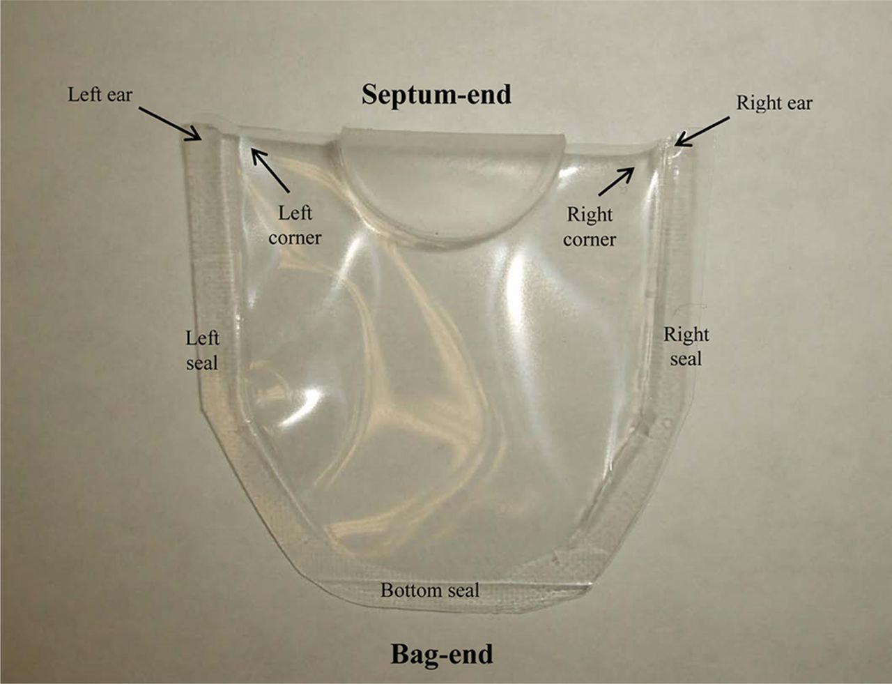
The product is the aqueous solution formulation of the rapid acting insulin analogue, insulin aspart (NovoRapid®/NovoLog®) by Novo Nordisk A/S, Bagsværd, Denmark. The package consisted of a flat plastic laminate bag roughly 4 cm long by 4 cm wide, heat-sealed on three sides, and folded along the fourth edge. The fourth edge included an elastomeric disc or septum heat-welded in place. An empty bag is illustrated in Figure 1. In production practice, bags are filled with product and the filled bag seams are closed according to a proprietary form-fill-seal process. Filled bags are less than 1 cm thick. After filling and sealing, a metal clip is crimped onto the septum end of each bag.

Empty package with bag regions identified.
Preparation:
Product–packages used for test included a limited number of “Novo Nordisk–made” negative controls, which were product-filled bags without defect manufactured at Novo Nordisk A/S by their proprietary form-fill-seal procedure. These product–packages are referred to as “Novo Nordisk–made bags”. Most packages used for this research were manually filled and sealed at WAL according to the procedure described below. These WAL-made packages included both negative controls (without-defect bags) and positive controls (bags with intentional leaks).
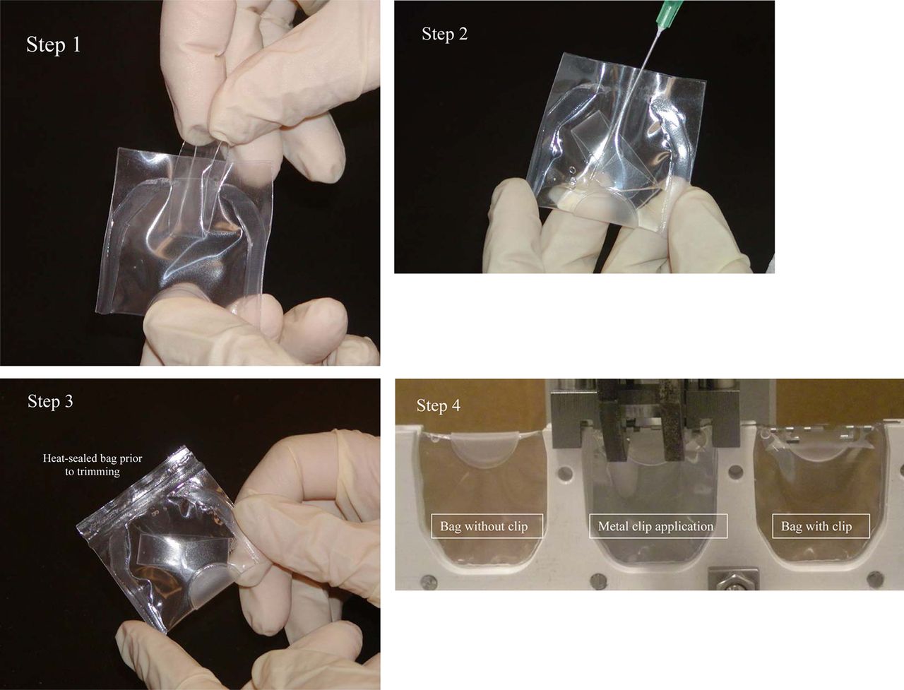
WAL package preparation started with semi-finished empty plastic bags supplied by Novo Nordisk A/S—open at the bag end, with left and right sides heat-welded closed. A coiled plastic film spacer was slipped into each bag through the unsealed open end to keep the bag walls apart during filling and sealing. Each bag was manually filled with approximately 3 mL of product, and then the open end was sealed shut using a laboratory bar sealer. Post-sealing, the curled spacer inside the bag was manually flattened so that it floated freely inside the bag. Excess plastic film around the heat-seal perimeter was trimmed away. For those test units requiring a metal clip, a mechanical crimping tool supplied by Novo Nordisk A/S was employed. The WAL product–package preparation procedure is illustrated in Figure 2.

Whitehouse Labs product–package preparation procedure.
Step 1. Insert a curled plastic strip spacer into an empty, semi-finished bag.
Step 2. Fill the bag with product solution.
Step 3. Apply a heat seal to the bag open end using a laboratory heat sealing unit. Manually press the curled plastic spacer flat. Trim off excess plastic around seal perimeter.
Step 4. Crimp metal clips onto designated “with-clip” bags with mechanical crimping tool.
Negative and Positive Controls:
Negative controls are packages with no known defect. All HVLD method development and validation studies utilized negative controls that were WAL-made or Novo Nordisk–made.
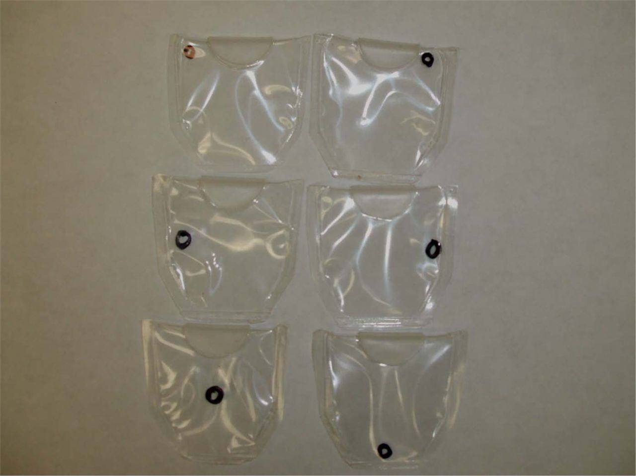
Conversely, positive controls are packages with known defects or leaks. Positive controls used for test method validation studies had hole defects created by laser-drilling through the plastic laminate film prior to package filling and bag-end sealing. Lenox Laser of Glen Arm, MD (7) was employed to create and size each hole (nominal diameter accuracy within ±2.5%). Holes were drilled in six different bag locations, as shown in Figure 3. Specific sizes of the positive control defects are detailed under Results and Discussion. The smallest holes were approximately 2.5 to 3.4 μm in nominal diameter. Smaller holes were not included due to laser-drilling technology limitations, coupled with the dimensional instability of smallest holes in flexible plastic film. The nominal diameters of the laser-drilled hole defects were determined by the hole manufacturer by comparing the air flow rate passing through the holes using air flow meters to the air flow rate passing through metal plate laser-drilled orifice calibration standards.

Positive controls—laser-drilled hole locations. Black circles on bags illustrating six laser drilled hole locations. From left to right—top row: left corner, right corner; center row: left seal, right seal; bottom row: center, bottom seal.
Test System
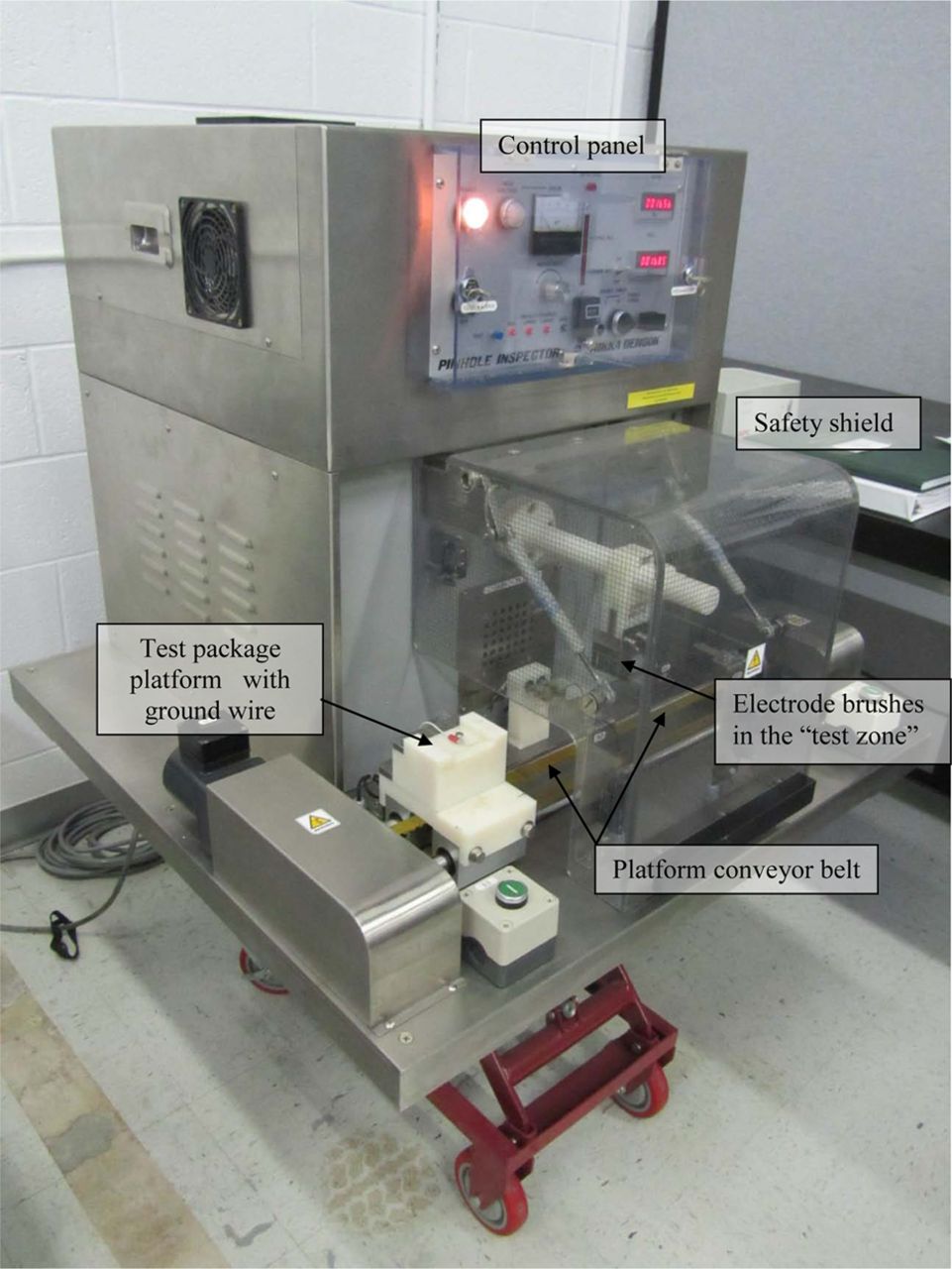
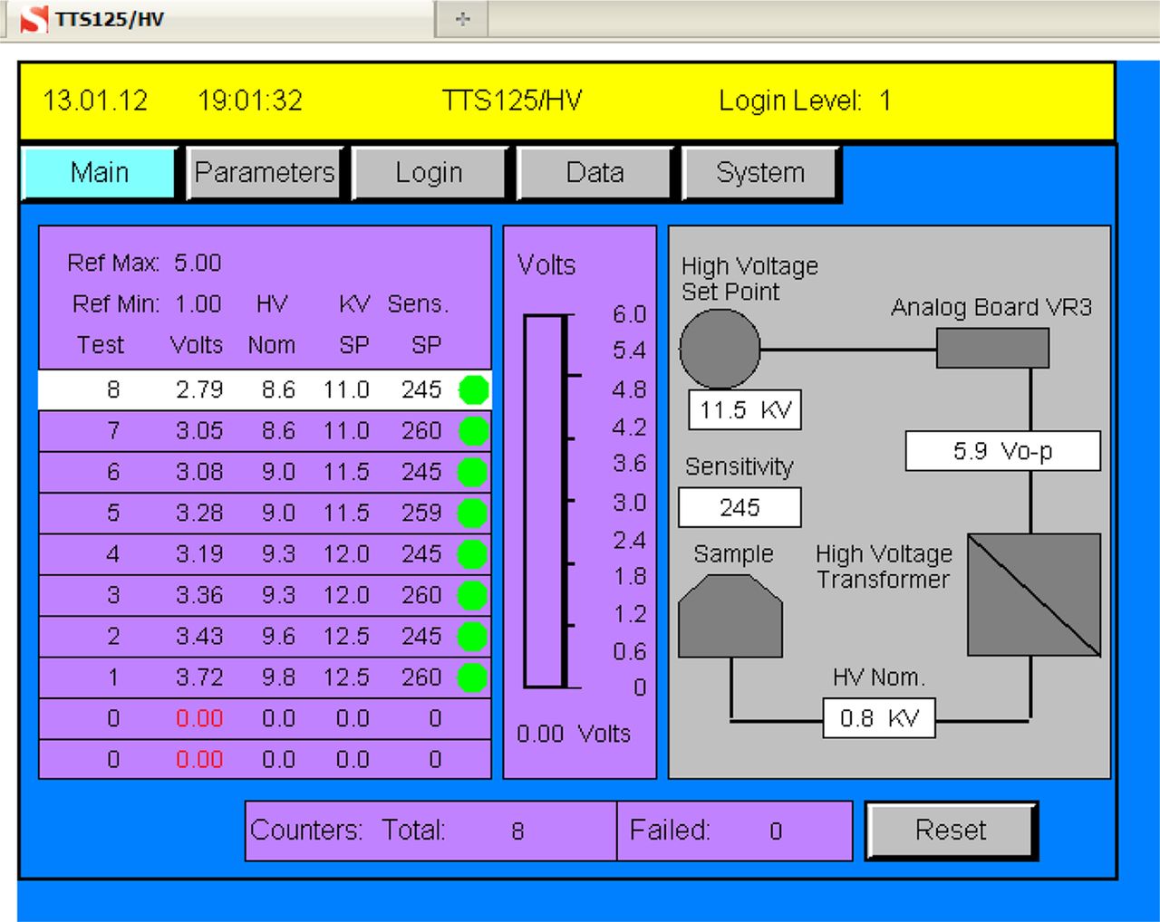
All HVLD tests employed an HDT-1 Pinhole Inspector manufactured by Nikka Densok, Inc. located in Kawagoe-shi, Saitama-ken, Japan. Pinhole Inspector support was provided by Nikka Densok USA, Inc. located in Lakewood, CO (8). TellTech Service Corporation in Mahopac, NY (9) was contracted to create and install an electronic data acquisition system to log HVLD instrument voltage and sensitivity adjustments and digitally capture test data using a remote laptop computer. The instrument with data acquisition system is illustrated in Figure 4. A screen shot from the test system data acquisition program, with a test system functional diagram, is shown in Figure 5.

HVLD unit by Nikka Densok USA, Inc.

HVLD digital acquisition screen shot with test method functional diagram to the right. Test results for tests 1 through 8 are displayed on the left.
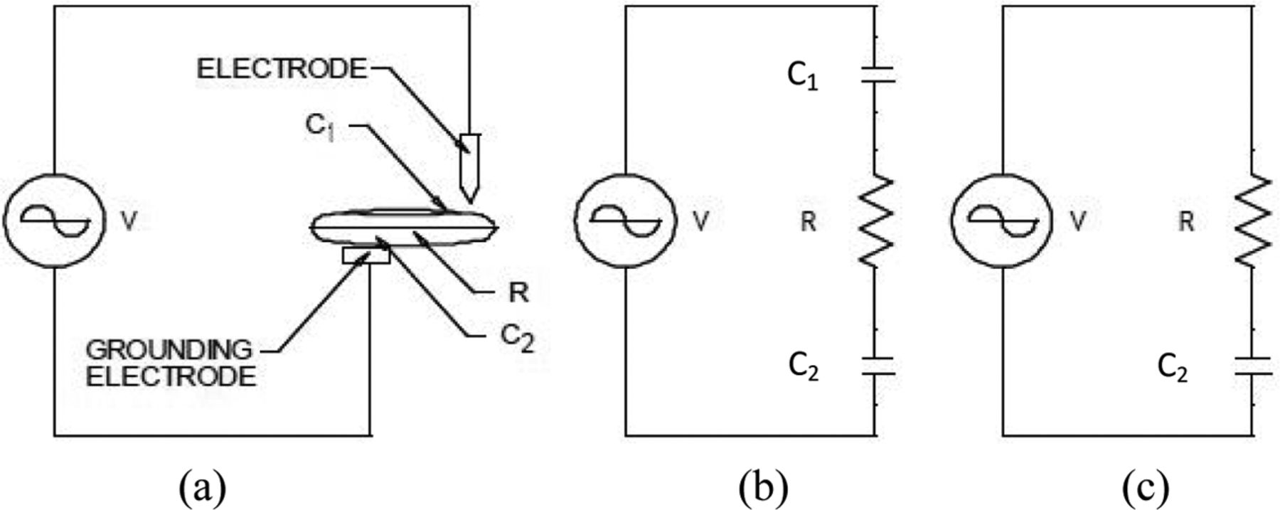
A functional diagram is provided in Figure 6. High-frequency high voltage (V) is applied to the product-filled container made of a nonconductive material. The high voltage generated in the instrument control section and boosted up in the high-voltage transformer is applied to the inspection electrode. A signal is sent to the inspection circuit through the detection electrode. If the container should have a leak, there will be an electrical discharge into the container. Detecting the change in flow of electrical current enables the presence of a defect to be recognized.

HVLD functional diagram. (a) The electrical equivalent of (b) and (c). (b) Circuit of an integral container (nonleaking). (c) Circuit of a defective container (leaking).
V = High voltage source.
R = Electrical resistance of product inside the container.
C1 = Volume of static electricity between the inspection electrode and the packaged product (capacitance).
C2 = Volume of static electricity between the ground electrode and the packaged product (capacitance).
In the current study the instrument HVLD test zone was set up by the manufacturer with a carbon bristle brush inspection electrode designed to sweep across the test package surface as it is conveyed through the test zone. A platform to cradle the package while being conveyed through the HVLD test zone was created by TellTech Service Corp. The platform was equipped with a metal screw electrically grounded to the HVLD unit. This test set-up was designed for integrity testing product–package clinical lots, for testing samples placed on long-term stability in lieu of sterility testing, and for exploring the feasibility of HVLD for 100% on-line production lot integrity testing.
Test Method Overview
Prior to operation the HVLD instrument is equipped with the appropriate test platform and test zone electrode brush (refer to Figure 4). The HVLD is turned on and allowed to warm up. The HVLD unit is programmed to predetermined test method operational parameter set points for high voltage (kV) and sensitivity (using a potentiometer scaled from 0 to 999). The HVLD unit is also programmed to judge test results according to predetermined quantitative reference maximum and reference minimum limits described below.
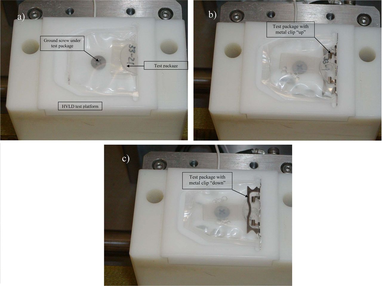
The test package is properly oriented and placed on the test platform. Three package orientations were employed: (1) packages with metal clip on and clip positioned up, (2) packages with metal clip on and clip facing down, and (3) packages with no metal clip. Figures 7A through 7C illustrate test packages with and without metal clips positioned on the HVLD test platform. The ground screw is visible beneath each package.

Test package orientations on the HVLD test platform.
a) Test package without a metal clip
b) Test package with a metal clip in the “clip up” position
c) Test package with a metal clip in the “clip down” position
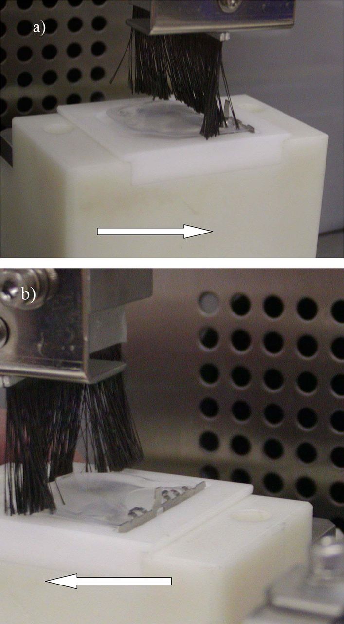
With the product–package unit in place, the operator activates the HVLD test, and the instrument conveyer carries the platformed unit through the instrument test zone. While passing through the test zone, the carbon electrode brush sweeps over the package causing the low-amperage, high-voltage alternating current (AC) generated by the HVLD transformer to flow from the brush, through and around the package, to the ground (Figures 8A and 8B). The HVLD signal frequency is fixed by the high voltage transformer and electronics. The frequency value is proprietary. As illustrated, packages were passed through the test zone either septum end first, or bag end first. The time required from test sample manual load to manual unload was approximately 3 s, including less than 1 s in the actual test zone. The HVLD unit is programmed to capture and measure the electrical current that passes through/by the container and reaches the ground, convert this current value to a direct current (DC) measurable signal, and display the final result in voltage units.

Test method directional scan options.
a) Test package with “clip up” entering the test zone septum first, in other words, moving from left to right.
b) Test package with “clip up” entering the test zone bag first, i.e., right to left.
The HVLD unit data acquisition system is programmed to evaluate the test results according to a predetermined, quantitative voltage reading operational verification limit (the Reference Minimum Limit, or “Ref Min”), and a predetermined quantitative voltage reading acceptance limit (the Reference Maximum Limit, or “Ref Max”). HVLD test results equal to or less than Ref Min serve as a warning indicator of possible system operation drift or test package misalignment. The Ref Max is the pass/fail voltage limit; HVLD test results equal to or greater than this upper limit value are deemed failures, indicative of package leakage.
For each test, the HVLD data acquisition system records and displays the high-voltage set point, the sensitivity set point, the Ref Min and Max limits, the final voltage measurement, and the pass or fail outcome (Refer to Figure 5 for a screen shot of the data capture system). System performance is verified at the start of each test period by testing a small set of negative control samples set aside for this purpose. All negative control test results should fall within the programmed Ref Max and Ref Min limits, and the high-voltage and sensitivity set points captured by the data acquisition system should match programmed settings.
Test Methods Development and Validation
Six different test methods were evaluated to identify the best way to detect leaks in the product-package by HVLD. These six methods included variables of test direction (testing septum end first versus bag end first), metal clip presence (on versus off), and metal clip orientation (up versus down). Specific Test Methods were assigned to each variable combination as indicated below. Ultimately, in actual practice each bag would only be tested twice: one time per each bag face surface.
Test Method 1. No clip, septum first
Test Method 2. No clip, bag first
Test Method 3. Clip up, septum first
Test Method 4. Clip up, bag first
Test Method 5. Clip down, septum first
Test Method 6. Clip down, bag first
Each test method required specific quantitative operational parameter high-voltage and sensitivity set points, and quantitative Ref Min and Ref Max Limits. Set points and limits for each method were established during test method development using negative controls.
A validation study was subsequently performed to verify each test method's ability to correctly identify negative and positive controls in a random population mix over multiple days of testing. Positive controls included bag hole leaks of various sizes at multiple bag surface locations. Method development and validation study details are included in the relevant Results and Discussion subsections.
Results and Discussion
Test Methods Development
High-Voltage and Sensitivity Set Points Selection:
An optimum test method requires that the high-voltage set point be set high enough to maximize electrical current reaching the ground, but not set so high that current arc from the electrode to ground occurs bypassing the package and generating a false-positive result. Once the optimum high-voltage set point is identified, an optimum range for the sensitivity set point is chosen. Based on the HVLD instrument manufacturer's recommendation, an optimum sensitivity range ensures voltage readings of approximately 3 V for no-defect packages (negative controls), while allowing for some set point adjustment in day-to-day instrument operation.
In the current study, it was quickly determined using negative controls that a high-voltage set point much greater than 13.0 kV for all six test methods risked current arc and should be avoided. Therefore, a series of tests was performed at high-voltage set points 12.0, 12.5, and 13.0 kV, at sensitivity set points adjusted in 5 unit increments to yield readings ranging from about 2 to 4 V. This process was repeated for each of the six test methods.
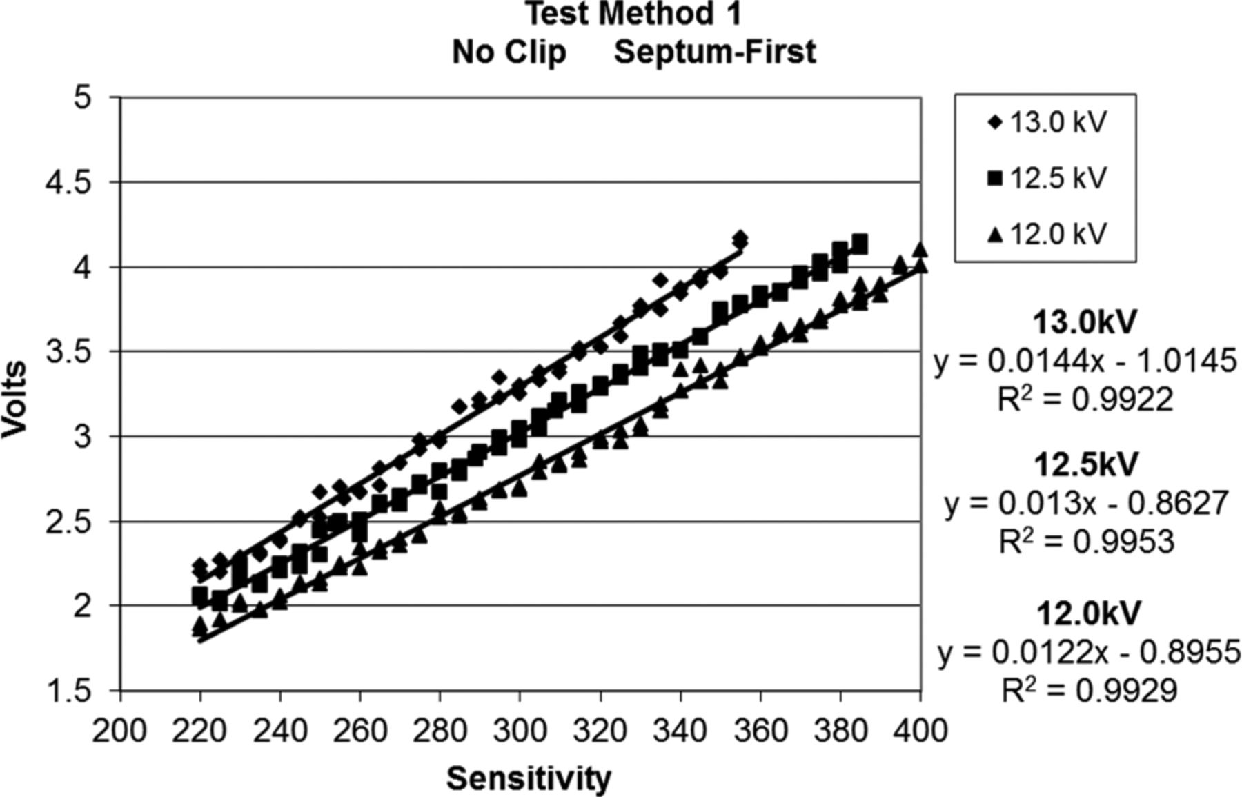
Test results for Method 1 are illustrated in Figure 9. All other test methods yielded similar results, demonstrating a strong linear correlation between sensitivity set point and voltage reading, at 12.0, 12.5, and 13.0 kV high-voltage set points. The linear regression analyses of voltage as a function of high-voltage and sensitivity set point for all six methods yielded regression coefficients ranging from 0.9695 to 0.9953. From these data, a high-voltage set point of 12.5kV was chosen. This 12.5 kV setting was low enough to avoid current arc yet was within a demonstrated optimal performance range, thus allowing for slight variation in actual high-voltage output.

HVLD Test Method 1—Voltage as a function of sensitivity and high voltage set points.
The sensitivity set point window for each test method was identified by first determining the sensitivity (x-axis) along the 12.5 kV linear regression corresponding to a 3 V reading (y-axis). Bracketing this sensitivity by ±5 units provided the sensitivity set point lower and upper range limits, listed in Table I.
HVLD Test Parameters, Test Methods 1 through 6
Ref Min and Ref Max Limits Selection:
Method development requires the establishment of appropriate pass/fail acceptance criteria for the HVLD voltage readings. This is done by repeatedly testing negative controls, employing optimized high-voltage and sensitivity parameters, to generate baseline voltage readings. These data are then statistically evaluated to predict both a lower limit (Ref Min), warning of system operation drift of test package misalignment; and an upper limit (Ref Max), the pass/fail voltage limit indicative of package leakage.
In the current study, population sets of negative controls were tested on each of three days (minimum) at the target high voltage set point (12.5 kV), and at the upper and lower sensitivity set points outlined in Table I, for each of the six test methods. Test packages included a subset supplied prefilled and sealed by Novo Nordisk A/S and a subset filled and sealed at WAL to account for product–package preparation variations. For a given method, the same package subsets were tested on each replicate test day. The total numbers of packages in each subset tested on each day by each method are outlined in Table II. With this negative control baseline information, the operational verification lower voltage limit (Ref Min) and the pass/fail voltage upper limit (Ref Max) for each test method were established.
HVLD Replicate Testing of Negative Controls
A high-level examination of the voltage readings obtained provides an indication of test method repeatability and precision for no-leak bags. As shown in Table III, day-to-day mean voltage readings within a test package subset (WAL versus Novo Nordisk—Columns A and B, respectively) agreed to within 3 standard deviation units of the mean values. Most agreed within 1 standard deviation unit. Novo Nordisk–made bags' voltage readings obtained over all test days matched the mean WAL-made bags' voltage readings within 2 standard deviation units or less (Column C). These results infer that there is little noticeable day-to-day difference in HVLD test results for any test method, and there is little, if any, difference in HVLD test results for WAL-made versus Novo Nordisk–made bags.
HVLD Precision—Differences among Test Days and between Bag Sources
Table IV includes an analysis of the voltage results from all bags (WAL-made plus Novo Nordisk–made) for each test method, pooling all data collected at both the lower and upper sensitivity range settings. As shown, the coefficient of variation for all negative controls tested according to Method 1 was 0.05. Similarly, the coefficients of variation for Test Methods 2 through 6 ranged from 0.05 to 0.06. Thus all HVLD test methods demonstrate similar degrees of precision when testing negative controls at 12.5 kV within the selected sensitivity ranges.
HLVD Test Results for Pooled Negative Control Populations, at Lower and Upper Sensitivity Set Points
Table IV pooled subset data were also used to calculate Ref Min and Ref Max limits for each test method. In other words, for each method the mean voltage ±3 standard deviation units range was calculated; the lower limit of this range was deemed to be the Ref Min, and the upper range limit was Ref Max. For example, for Method 1, the mean ±3 standard deviation units range is 2.47 to 3.43 V. The lower limit (2.47 V) is the Method 1 Ref Min—the operational verification limit. HVLD test results equal to or less than this value warn of possible system operation drift or test package misalignment. The upper limit (3.43 V) is the Method 1 Ref Max—the pass/fail voltage limit. HVLD test results equal to or greater than this value are indicative of package leakage. The test parameters and reference limits for all six test methods are summarized in Table V.
HVLD Test Methods
Test Methods Validation
Protocol:
All six test methods outlined in Table V were validated for robustness and limit of detection confirmation. For each test method, the protocol required a 50:50 random mix of positive and negative controls be tested on each of three replicate test days. The positive controls included holes approximately 3, 5, and 10 μm in nominal diameter—the number of units tested per day being equally divided among hole size group and hole site location. (Note: The actual defects in each hole size group ranged from 2.46 to 3.40 μm, 3.94 to 7.01 μm, and 8.31 to 11.17 μm for the entire positive control population. For hole site locations, refer to Figure 4.)
The number of test units for each Test Method 1 and 2 (employing bags with no metal clip) included 54 negative controls, plus 54 positive controls to account for all three hole size groups and six bag hole site locations. The number of test units for each of the Test Methods 3 through 6 (employing metal clipped bags) included 18 negative controls, plus 18 positive controls to account for the three hole size groups and the two bag hole site locations investigated. (Note: Metal-clipped positive controls had holes only at the septum end right and left bag corners, to check the impact of metal clips near these hole sites.)
Positive controls required for each of the three replicate test days were filled and sealed the day of testing to eliminate possible storage time effects and to minimize liquid product leakage loss. Each positive control was tested only once to eliminate possible hole size change from repeated HVLD exposure. [Note: Experiments performed prior to method validation found laser-drilled hole size widens as a function of HVLD exposure count. For example, holes averaging approximately 6.5 μm (±1.4) in nominal diameter widened to about 11.0 μm (±0.8) after 6 test exposures (n = 10).]
For each test method, all positive controls were tested at the lower sensitivity range set point (to maximize false-negative result risk), and all negative controls were tested using the upper sensitivity range set point (to maximize false-positive test result risk). Thus the robustness of each method at operational setting extremes could be confirmed.
The protocol acceptance criteria for each test method were as follows.
All negative controls must pass all tests.
The test method's limit of sensitivity will be based on the smallest hole size consistently detected as leaking (fails). All positive controls with holes equal to or larger than the demonstrated limit of sensitivity must fail all tests.
Results and Discussion
Method validation results for Test Methods 1 through 6 are summarized in Table VI. In short, the large majority of tests met the acceptance criteria specifying all negative controls must pass, and all positive controls with holes sized at or above the demonstrated limit of detection must fail. However, some exceptions occurred as noted below. The incidence rates of false-positive/negative results are also summarized in Table VII.
HVLD Test Method Validation Results
Validation Study—False-Positive and False Negative Results
Negative controls failed (false-positive results) in Methods 1 and 6.
Method 1. Two bags yielded voltage readings of 3.43 V and 3.52 V, which were at or slightly above the Method 1 Ref Max of 3.43 V.
Method 6. One bag yielded a reading of 3.31 V, as compared to the Ref Max of 3.30 V.
Positive controls passed (false-negative results) in Test Methods 2, 4, and 5.
Method 2. Bag 124 had a right corner hole (5.81 μm) located in a concavity on the collapsed bag surface.
Method 4. Bag 38 had a right corner hole (3.20 μm) located in a concavity on the collapsed bag surface.
Method 5. Bag 114 had a left corner hole (6.44 μm) located on the collapsed bag about 3 mm directly beneath the bag's metal clip.
No one method performed remarkably better than the others. The low-false positive rate observed for the negative controls was not surprising, given the Ref Max limit was set 3 standard deviation units greater than the observed negative control mean. In practice, the occasional suspect false-positive result in a normal distribution population can be dealt with either by retesting the test package to confirm the original results, or by rejecting the package outright. (Negative controls used for method development and validation were including in multiple experiments, exposing them to repeated tests. The two bags that failed during validation were retested in later experiments and found to pass. In routine practice, any suspect package retests should be preceded by system performance verification tests.)
Data suggest the rate of false rejects could also be reduced by raising the Ref Max limit to >3 standard deviation units above the mean. However, broadening the acceptance criteria was not considered at the time these tests were performed. Additional research was felt necessary to fully understand the method's ability to accurately screen out other types of package defects, and to determine the impact of other variables on voltage readings, including package storage conditions and package material lots (not available at the time of these tests). Given the information and data available, all Test Methods 1 through 6 were judged to have met the first acceptance criterion.
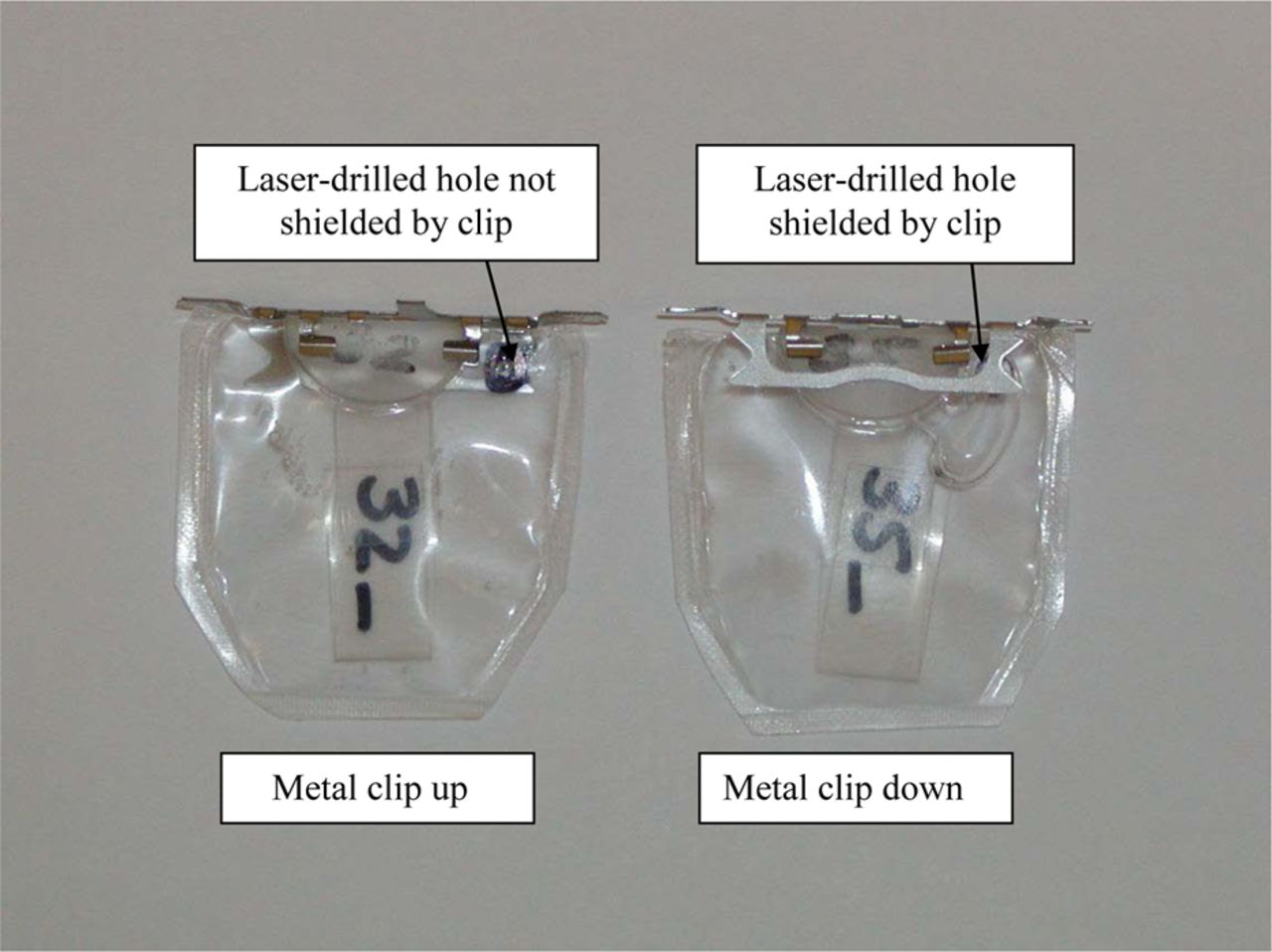
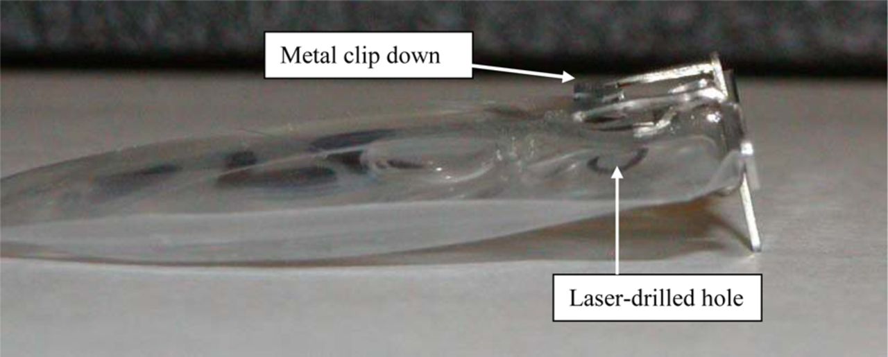
The incidence of false-negative results (leaking bags that passed) was also low. However, the results did not correlate to hole size, as one might expect, as only one of 60 bags in the 3 μm hole size subset falsely “passed” (Method 4). Rather, physical examination of the three bags yielding false-negative results implied that the outcomes may be due to the inability of the HVLD electrode brushes to come close enough to the package holes. In all three cases, the bags were somewhat collapsed perhaps due to low fill or product leakage, and all holes were located in the corners. Additionally, in Method 5, the metal clip was positioned over the bag corner hole, creating a 3 mm air gap between the hole and the clip. Figures 10 and 11 demonstrate the gap that could occur between a partially collapsed bag hole and the metal clip, hampering HVLD electrode brush proximity. Figure 12 illustrates a hole located in the valley of a partially deflated bag. In this case, HVLD electrode brushes might sweep over the concavity, missing the hole.

Positive controls with laser drilled holes in the bag right corner, with metal clip attached “clip up” (left) and “clip down” (right). The metal clip can potentially shield the hole from the HVLD electrode brushes, especially if the bag is partially deflated due to product leakage or low fill.

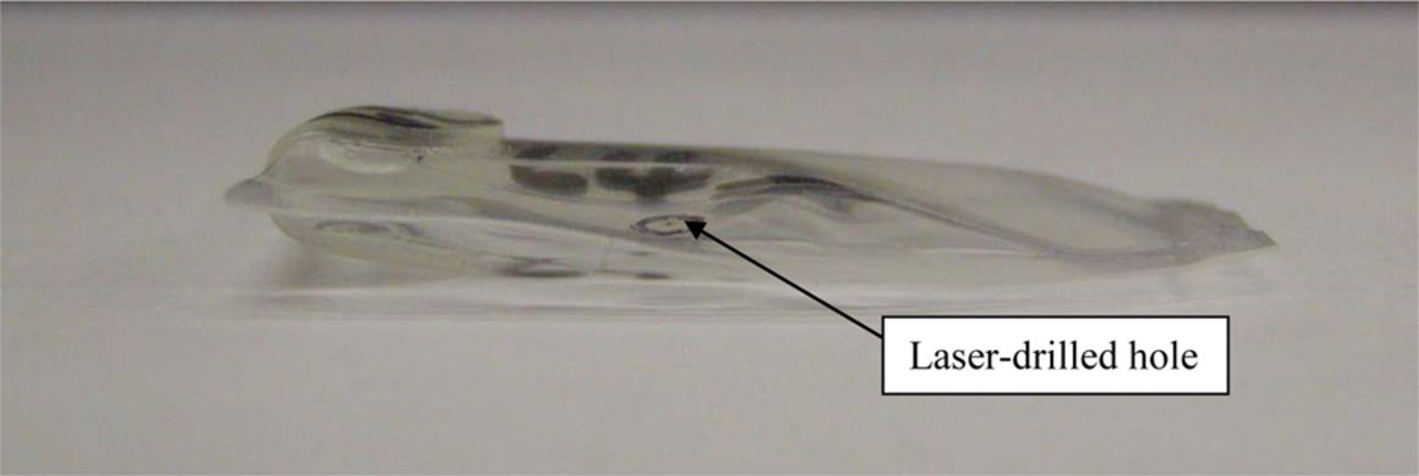
A positive control (clip down) with a laser-drilled hole in the bag right corner. Note the air gap between the hole (circled) in the partially collapsed bag and the metal clip. In this case, the metal clip may shield the hole from HVLD electrode brush contact, especially when tested in the septum end first direction.

A positive control (no metal clip), with a laser drilled hole near the bag left seal. The hole (circled) is located in a cavity or “valley” of the partially collapsed leaking bag.
Before drawing any conclusions concerning the test methods' conformance to the validation protocol's second acceptance criterion, two follow-up experiments were performed to investigate the theory that a positive control hole, otherwise detectable by HVLD, can evade detection upon bag leakage and collapse.
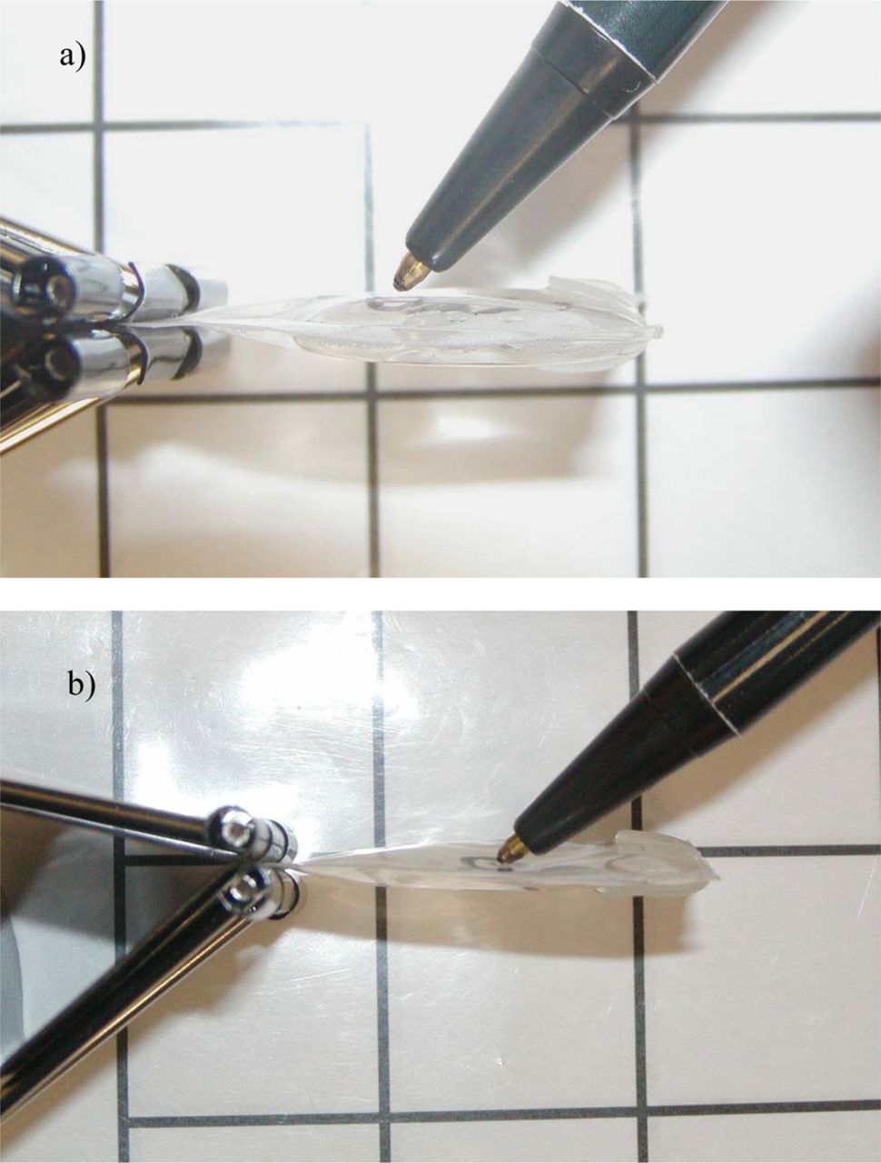
Experiment 1 used five bags with no metal clip, each with a single hole approximately 5 μm in nominal diameter (actual range = 4.96–5.94 μm) near the seal edge. Three bags had right seal holes, and two had left seal holes. Immediately after filling/sealing, the approximate thickness of the positive control bags at the hole site ranged from 3.2–4.9 mm (see Figure 13a). Nine negative controls were also included.

Product-filled bags with a circled hole near the right seal (pen indicating hole location). (a) Bag before leakage, and (b) bag deflated or collapsed from large leakage.
All packages were leak tested via Test Methods 1 and 2. Leak tests were first performed on all units immediately after fill-and-seal prior to product leakage and bag collapse (stage 0). Each positive control bag was then gently squeezed to force product out of the hole (stage 1). Subsequently, bags were pricked with a 21-gauge injection needle at the laser-drilled hole location to permit greater liquid leakage. These largely leaking bags were squeezed twice more to force additional leakage (stages 2, 3), and then finally squeezed to full bag collapse (stage 4). The approximate thickness of fully collapsed positive control bags at the hole sites ranged from 0.8 to 1.4 mm (see Figure 13b). HVLD tests were performed at each stage of bag collapse. A negative control was tested after each positive control “failing” leak test result to verify that the test system was correctly functioning and had not been contaminated with leaking product.
Positive control test results are summarized in Table VIII. All positive controls failed both Methods 1 and 2—leakage was detected—from Stage 0 though Stage 1. By Stage 2, two packages passed (100, 101)—these leaks were no longer found. By Stage 3, package 91 passed, with Method 2 voltage results below Ref Min. By Stage 4, package 102 HVLD reading fell below the Ref Min limit. Only package 93 continued to fail by both Methods 1 and 2 after full bag collapse. These results support the theory that HVLD may pass a largely leaking bag due to bag deflation or collapse and the inability of the electrode brush to contact the package leak site.
HVLD Test Results for Collapsed Positive Controls
Experiment 2 used positive controls each with a single laser-drilled hole located under the metal clip. Two hole-size sets were included. One set had holes about 5 μm in nominal diameter (4.01–5.78 μm), and the other had holes about 10 μm in size (8.36–10.64 μm). Negative controls were also included to verify HVLD baseline performance. All bags were tested by “clip-down” Methods 5 and 6. No positive control was tested more than once. Positive controls were HVLD leak tested within about 15 minutes of filling/sealing to ensure that the bags were still essentially full of product, not collapsed from leakage. Results summarized in Table IX show all positive control leaks were found by HVLD (units failed), and all negative controls passed.
HVLD of Essentially Full, With-Clip, Positive Controls
These two experiments demonstrate that hole defects can be found by the HVLD methods described, as long as test packages remain essentially full of product at time of test allowing the HVLD electrode bristles to sweep near the bag defect or the metal clip shielding the defect. If the bag has deflated, HVLD may miss largely leaking packages. Such false-negative results can be avoided in practice by ensuring proper package fill and by screening for largely leaking or deflated packages prior to HVLD testing.
HVLD test results as a function of bag collapse lend support to the hypothesis that all three false-negative test results that occurred during test method validation were likely caused by bag collapse or low package fill, thus limiting HVLD electrode brush access to the hole site. Given this information, Test Methods 1 through 6 all met the validation protocol acceptance criterion that all positive controls with holes equal to or larger than the demonstrated limit of sensitivity must fail all tests, with the caveat that all packages must be essentially full at the time of test. The limit of detection was demonstrated to be approximately 3 μm, with the smallest hole detected being 2.46 μm in nominal diameter. While HVLD may be able to detect smaller defects, smaller holes were not included due to limitations in hole creation technology coupled with the dimensional instability of such tiny holes when formed in flexible plastic film.
Conclusion
HVLD leak test methods were successfully developed and validated for their ability to accurately differentiate product-filled plastic laminate film bag packages with or without defects as small as approximately 3 μm in nominal diameter. A total of six different methods were validated, enabling leak detection of packages with or without a metal clip, with the asymmetric clip facing either up or down, with packages passing through the HVLD test zone either septum end or bag end first.
No method appeared to provide a testing advantage. All methods were proven to be robust and adequately sensitive. The pass/fail criteria were so established that a small risk of falsely failing no-leak packages was inherent in the test methods. Such risk can be mitigated by retesting any failed packages, or rejecting all such packages outright to prevent chancing the release of any defective packages. Some risk of falsely passing a defective package was found to occur only if the package was collapsed due to low fill or product leakage. This risk can be avoided by screening packages for proper fill level or size prior to leak detection.
Part 2 will investigate the ability of HVLD to identify leaks located in the bag heat seal. In addition, the influence of bag long-term storage on hole detection will be examined, and the impact of chilled bag temperature and bag film lot on HVLD baseline results will be checked. Part 3 will report the effect of HVLD exposure on drug product visual appearance and chemical stability.
Glossary of Terms
High-voltage leak detection (HVLD)—A method of package leak detection requiring the electrically conductive product solution to be contained in a relatively nonconductive package. Electrically grounded product–packages are exposed to a high-voltage, low-amperage current. Current that passes from the source through the packaged product and along the package walls to the ground is measured as voltage. A leaking package with product solution located in or near the leak triggers a marked increase in voltage reading.
HVLD—See high-voltage leak detection.
Leak—A gap or defect in a package wall capable of permitting fluid flow into or out of the package. In this study, positive control leaks were artificially created via laser-drilling technology.
Negative controls—Product–packages with no known package leak.
Positive controls—Product–packages with an intentional package leak.
Reference Maximum Limit (Ref Max)—A predetermined quantitative voltage acceptance limit by which HVLD test results are judged as pass or fail. An HVLD voltage reading greater than or equal to Ref Max is indicative of test package leakage (test failure).
Reference Minimum Limit (Ref Min)—A predetermined quantitative voltage acceptance limit by which HVLD test results are judged. An HVLD voltage reading less than or equal to Ref Min warns of possible system operation drift or test package misalignment.
Conflict of Interest Statement
The authors declare that they have no competing interests.
Acknowledgements
The authors wish to acknowledge Mr. Eric Creveling of Whitehouse Laboratories for his invaluable technical expertise and assistance throughout all phases of this project.
- © PDA, Inc. 2013


Jump to section
Related Articles
Cited By...
More in this TOC Section
Similar Articles
Keywords
- Container-closure
- container-closure integrity
- Defects
- Electrical conductivity and capacitance leak detection
- Form-fill-seal packages
- High-voltage leak detection
- HVLD
- Leak
- Leakage
- Leak detection
- Leak test method
- Package
- Package defects
- Package integrity
- Package integrity method
- Plastic laminate bag
- Protein product
- stability
- Insulin.