
Abstract
Glass vials have been used as primary containers for parenteral drugs including biopharmaceuticals. Different types of glass-related particles, although in low occurrence rate, may be adventitiously introduced in these parenterals. Proper classification and investigations of these glass-related particles may help to understand their formation, improve process control, reduce glass-related particles, and deliver safe parenteral drugs to patients. In this article, we introduced a classification scheme, and identification procedures and methods, for the glass-related particles. We propose to classify them as glass chip, glass lamella/flake, and silica gel. Eight characteristics for each glass particle type have been identified and described for the visual inspection method. The limitations of the visual method and the need to correlate visual results with forensic analysis are discussed. Using representative examples from each type of glass particle, this study summarized their forensic differentiations based on microscopic methods of optical microscopy, scanning electron microscopy, micro-flow imaging, and spectroscopic methods of dnergy-dispersive spectroscopy and Fourier transform infrared spectroscopy. The mechanisms of glass particle formation are listed as references for drug development scientists to investigate the root causes and improve process control on visible glass particles in parenteral vials.
LAY ABSTRACT: Glass vials have been used as primary containers for parenteral drugs including biopharmaceuticals. Different types of glass-related particles, although in low occurrence rate, may be adventitiously introduced in these parenterals. Proper classification and investigations of these glass-related particles may help to understand their formation, improve process control, reduce glass-related particles, and deliver safe parenteral drugs to patients. In this article, we introduced a classification scheme, and identification procedures and methods, for the glass-related particles. We propose to classify them as glass chip, glass lamella/flake, and silica gel. Using representative examples from each type of glass particle, this study summarized their forensic differentiations based on microscopic and spectroscopic methods. The mechanisms of glass particle formation are listed as references for drug development scientists to investigate the root causes and improve process control on visible glass particles in parenteral vials.
Introduction
Parenteral drugs including biopharmaceuticals often use glass vials as primary containers. The presence of visible particles in parenteral products may potentially present a safety concern to patients (1). One of the top 10 reasons for parenteral product recall is the presence of visible particles (2). Pharmaceutical manufacturers are responsible to ensure the suitability of the glass vials for their products and processes. General chemical inertness, physical and dimensional stability, and excellent transparency have been the basis for the use of glass as containers for pharmaceutical products. The primary glass containers are not supposed to interact physically or chemically with the contents (3). However, glass is not completely inert, and it can be attacked by different solution media (4, 5, 6). Its performance is affected by the manufacturing process of vials made from glass tubes (7). In September 2010, Amgen and the U.S. Food and Drug Administration (FDA) notified health care professionals that certain lots of Epogen and Procrit (Epoetin alfa) vials were recalled, as a precaution, because the vials may contain extremely thin glass flakes (lamellae) that are barely visible (8). Bedford Laboratories voluntarily recalled one lot of 20% acetylcysteine solution vials because of the presence of glass particles in February 2012 (9). Visible glass particles have received increasing attentions from the regulatory agencies as a potential safety issue. A recent FDA communication has recommended that drug manufacturers re-examine their supplier quality management programs with the glass manufacturers to assure that glass lamellae are not occurring (10).
In the life cycle of parenteral products, the inner surfaces of glass containers are subject to various stresses including chemical, thermal, and mechanical stress. These stresses may lead to generation of a variety of glass particles with different size, shape, and morphology. Various terms within our company have been used to describe and name these particles, including glass shard, shiny, granular, gel, cotton-like, irregular, amorphous, sheet-like, needle-like, flake-like, chip, chunk, and lamellae by employees from different organizations including research & development, manufacturing, and quality. This has caused confusion and complicated root cause analysis and process improvements. From our experience of handling these particles, we proposed to classify all observed glass-related particles into three main categories or types as glass chip, glass lamella/flake, and silica gel based on their physical and chemical characteristics.
It is often straightforward to differentiate glass-related particles from non-glass particles simply based on morphology and chemical or structural analysis. However, it is challenging to classify the glass-related particles into the proposed three different types, as they are all derived from glass surfaces and have major elements of Si and O, and have Si-O as the major functional group. This study firstly describes the characteristics of each glass particle type, and then proposes analytical testing strategies to characterize and confirm the presence of these particles. Although this study was focused on glass vials, these classification and mitigation methods may also be applicable to other glass containers such as syringes, cartridges, and ampoules.
Materials and Methods
Five representative vials were selected in this study. For each of three types of glass particles, one representative vial was selected and filtered for optical microscopy (OM), scanning electron microscopy (SEM), energy-dispersive spectroscopy (EDS), and Fourier transform infrared (FTIR) spectroscopy. Another two representative vials with glass lamellae and silica gel respectively were used for micro-flow imaging (MFI) without filtration. The vial with glass chip has one particle and the vials with lamellae or silica gel particles have multiple particles.
Particle Isolation on Filters
All the vials involved in this study have biopharmaceutical formulations in them with or without active biopharmaceutical drugs. Glass particles were isolated by filtration under a laminar flow hood. The filter was rinsed several times with Milli-Q water prior to filtration. A polycarbonate 0.2 μm pore size filter (Isoprene, catalog #GTTP02500, Millipore, Billerica, MA) was used to filter the content of each vial with particles of glass chip, glass lamellae, or silica gel for SEM testing, while for all other tests gold-coated filters (0.8 μm pore size, Filtr.AID, Catalog #RGG1010008_e, Rap ID, Berlin, Germany) were used. The particles retained on the filters were further washed with Milli-Q water before examination by optical microscopy. No further particulate manipulation was performed for the glass lamellae and silica gel particles. FTIR spectra of micro-particles were obtained directly on the gold-coated filters. The glass chip particle was transferred onto a NaCl disc and covered with another disc for FTIR measurement in transmission mode.
Optical Microscopy (OM)
Particle Morphology:
Particles isolated on the gold-coated filters were first examined with a Zeiss Stemi 2000 stereomicroscope. The optical images of particles were captured using a color digital camera attached to the microscope and recorded by a computer. The glass chip was isolated from a vial with Protein Drug Product A, 70 mg/mL, 10 mM sodium acetate, 5% sorbitol, 0.004% polysorbate 20, pH 5.2; the glass lamellae from a vial with Protein Drug Product B, 30 mg/mL, 10 mM sodium acetate, 5.0% sorbitol, 0.004% polysorbate 20, pH 5.2; and the silica gel from a vial with placebo for Protein Drug Product C, 160 mM arginine, 10 mM potassium phosphate, 0.004% Tween 20, pH 7.0.
Vial Surface Examination:
The vial that contained the glass chip was also checked for damage in its inner surface. The image was recorded by the same the Zeiss Stemi 2000 stereomicroscope coupled with the color digital camera.
Scanning Electron Microscopy (SEM)
Particle Morphology:
A Zeiss EVO 40 SEM (Carl Zeiss Microscopy, LLC, Thornwood, NY) was used to image the samples by a secondary electron detector in variable pressure mode. The SEM electron source has an excitation voltage of 20 keV for glass chip and silica gel. For SEM imaging, the glass chip and the silica gel particles on separate gold filters were directly put into the SEM sample chamber to retain particle morphology. The glass chip and the silica gel particles were the same samples that were examined by the OM. For glass lamella, as it was much more challenging to image such a thin layer, a polycarbonate filter was used instead of a regular gold-coated filter. The excitation voltage for the electron source was selected as 5 keV to reveal more surface details of thin samples. The glass lamellae were from a product vial with Protein Drug Product A, 70 mg/mL, 10 mM sodium acetate, 5% sorbitol, 0.004% polysorbate 20, pH 5.2.
Vial Surface Examination:
Two vials, with the abovementioned glass lamellae and silica gel in OM, were examined for delamination defects on the inner surfaces. For interior vial surface analysis, the vials were cut into long strips by a diamond saw along the sidewalls. The strips were then mounted on double-sided carbon tabs. The examined areas were focused on the sidewall above and under the filling lines.
Micro-Flow Imaging (MFI)
The MFI instrument used in this study is a DPA 5200 system (ProteinSimple, Santa Clara, CA) with a 100 μm silane-coated flow cell using SP3 set point. This instrument uses 1 mL barrier tips to introduce a particle-containing liquid sample into the sample inlet port and employs digital image analysis to count liquid-dispersed particles. Briefly, the liquid sample is pumped by a peristaltic pump through a flow cell and imaged by a sensitive digital camera. The threshold for object detection is set at a greater than 4% light intensity difference between background light and light affected by the presence of particles. Once this threshold is reached, the image of the object detection will be recorded and counted in the distribution. System suitability is performed using National Institute of Standards and Technology (NIST)-certified 5, 10, and 15 μm polystyrene beads to ensure that the sizing and counting accuracy is within predefined limits.
Prior to testing on the instrument, all samples were degassed at 75 torr for 1 h to eliminate microscopic air bubbles in the liquid. During testing, approximately 0.8 mL of liquid was removed from the sample vial by a pipette and mounted on the MFI sample inlet port. In addition to size and counts, particle morphology properties were also analyzed and recorded. The glass lamellae samples for MFI study were from a vial of Protein Drug Product D, 3 K U/mL in 0.25% human serum albumin, 100 mM NaCl, 20 mM sodium citrate, pH 6.9; and the silica gel samples were from Protein Drug Product C Placebo, 160 mM arginine, 10 mM potassium phosphate, 0.004% tween 20, pH 7.0.
Energy-Dispersive Spectroscopy (EDS)
The EDS samples were the same as SEM samples. The SEM unit was used to find the particles on the filter and provide the excitation electron sources with an excitation voltage of 20 kV. For EDS analysis, the particles on the gold-coated filters were directly put into the SEM chamber secured with double-sided copper adhesive tapes. The EDS samples were the same as SEM samples. The SEM unit was used to find the particles on the filter and provide the excitation electron sources with an excitation voltage of 20 kV. An Oxford INCA Energy 300 EDS (Oxford Instruments, Elk Grove Village, IL) attached to the SEM was used for the elemental analysis.
Fourier Transform Infrared (FTIR) Spectroscopy
FTIR analysis was performed with a Bruker Hyperion 3000 microscope attached to a Tensor 27 FTIR spectrometer (Bruker Optics, Billerica, MA). FTIR spectra were collected in reflectance or transmission mode with 128 scans and 4 cm−1 resolution. The silica gel and glass lamella particles were from the same filters as examined with OM. The particles on separate gold-coated filters were directly placed under the FTIR microscope, and the IR signals were collected in reflectance mode where the IR light source passes through the samples twice with an incident angle of 66–90°. For glass chip, the glass chip particle used in OM was very thick, and signals saturated the detector. The FTIR measurement needed a thinner sample to have a reliable signal. Another relatively thin glass chip particle was filtered from a vial with Protein Drug Product E, 25 mg/mL, 51 mM sodium phosphate, 60 mg/mL α,α-trehalose dihydrate, 0.04% (w/v) polysorbate 20, pH 6.2. The particle was sandwiched between two IR-transparent NaCl windows. The IR signals were collected in transmission mode where the IR light source passes through the sample only once.
Results
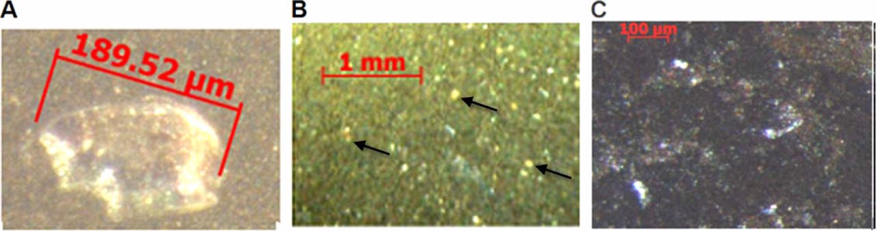
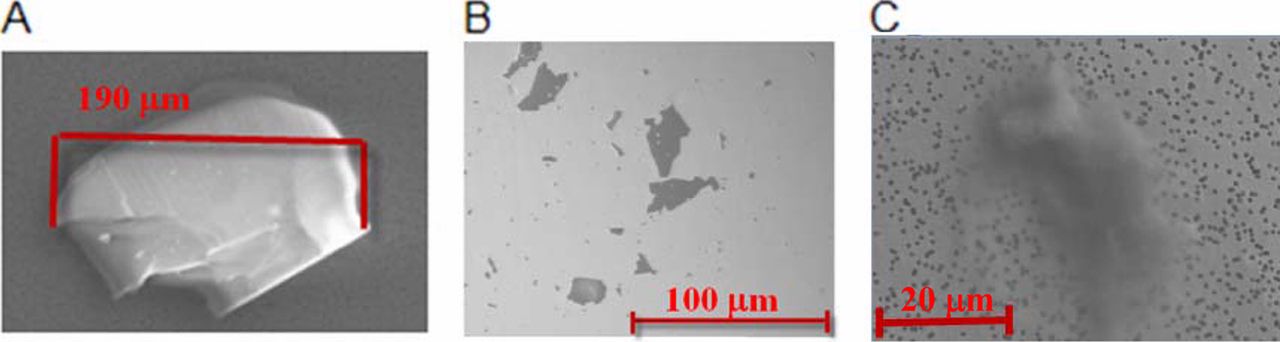
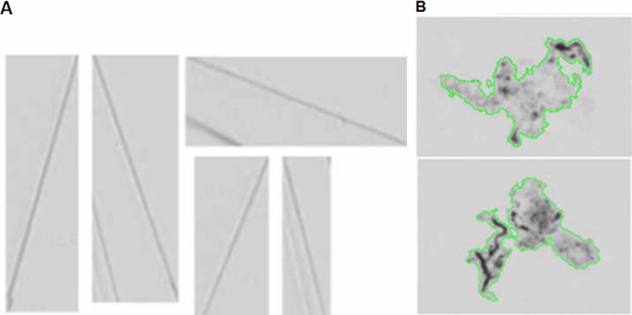
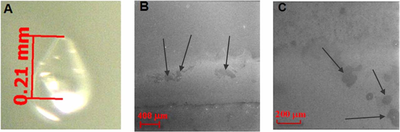
OM examinations of filtered particles provided optical and morphological differences among the three representative particles. Both glass chips (Figure 1A) and glass lamellae (Figure 1B) can be shiny, with glass lamellae appearing flat without the three-dimensional contour of the glass chips. The silica gel particles (Figure 1C) are white, discrete, and powder-like. The three particle types have very distinctive SEM images, as demonstrated with the representative SEM images for these glass particles (Figure 2). The glass chip (Figure 2A) has a distinct three-dimensional contour line with an irregular shape due to the breakage from the vial. The glass lamellae have a two-dimensional flat structure (Figure 2B), and the larger ones could be even folded (data not shown). The silica gel (Figure 2C) showed morphology of dried, fluffy gel with an uneven surface. The small black holes on the filter of silica gel came from the filter pores with a size of about 0.8 μm. Typical MFI images for glass lamellae and silica gel particles are shown in the Figures 3A and 3B. The contours of gel particles are marked out by green lines in Figure 3B. Glass lamellae are transparent, often anisotropic, and with sharp edges, whereas silica gel particles are often amorphous. Because glass chips often sink to the bottom of the container, and also due to their extremely low concentration, they are typically not detected with MFI analysis.

OM pictures of (A) glass chip, (B) glass lamellae, and (C) silica gel. The three arrows in panel B indicated the positions of three representative glass lamellae.

SEM images of (A) glass chip, (B) glass lamellae, and (C) silica gel.

MFI images of (A) glass lamellae and (B) silica gel. The contour of the gel particles are marked by green color lines.
For the glass chip particle, the related vial interior surface was carefully scanned under OM for possible damage as a result of the glass chip breakage. In the shoulder area, a defect was found right at the joint line between shoulder and sidewall, as shown in Figure 4A. Due to the curved shape of the shoulder and the shiny spots of the lighting, no clear image could be easily obtained, but the defect site was still quite apparent. The inner surface of the glass vial with lamellae particles were examined under SEM by secondary electron imaging. Surface defects near the sidewall close to the bottom of the vial showed a defect of horizontal line with some patchy defects (Figure 4B). These surface defects on the vial inner surface supported the conclusion that the thin-flat glass lamellae were peeled off from glass vial surface due to chemical or mechanical stresses. The inner surface of the glass vial with gel particles was also examined under SEM by secondary electron imaging, and similarly patchy defects were also found on the sidewall close to bottom of the vial (Figure 4C). We had to rely on the differences of lamellae with silica gel particles in Figures 2 (SEM), 3 (MFI), and 5 (EDS) to classify lamellae from gel particles. No such defects were found above the filling line on the sidewall of both vials in Figures 4B and 4C.

(A) OM of the vial shoulder defect from glass chip breakage, (B) SEM of the vial surface defects from glass lamellae generation, (C) SEM of the vial surface defects from silica dissolusion. The arrows in panels B and C indicate the positions of patchy defects.
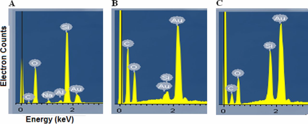
The Type 1A glass vials that Amgen used have a glass composition of 80% SiO2, 4% Al2O3, and 2% Na2O. In EDS analysis, glass-related particles should have elements Si and O present, and in some cases Na and Al for glass chips, as demonstrated from an EDS spectrum of glass chip (Figure 5A). The gold-coated polycarbonate filters are expected to contribute Au, C, and O signals. The glass chip (Figure 5A) has very strong Si and O peaks, with traces of Na and Al. Compared with glass chip and silica gel, glass lamella has a much weaker Si signal. The majority of the signal for the O element could come from the filter membrane underneath the particles, as the glass lamella is very thin (Figure 5B). Identification of the glass lamellae mainly relies on detection of Si element if they are on this type of filter membranes that contribute O signal. The silica gel also has very strong Si and O (Figure 5C); this is expected as it is silica gel and composed of polymerized silicic acids (11).

EDS analysis of (A) glass chip, (B) glass lamella, and (C) silica gel.
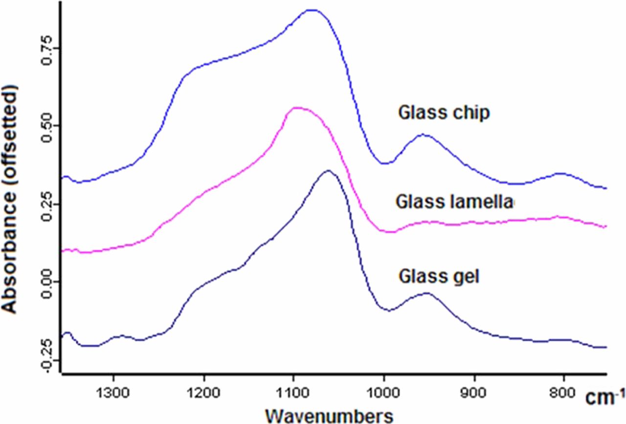
The FTIR spectra of the glass lamella and the silica gel were usually collected by reflectance modes directly on gold-coated filters, and the FTIR spectra of glass chip was collected in transmission mode (Figure 6). The most characteristic peaks for all three types of glass particle types are the Si-O asymmetric stretching from SiO2 between 1050 and 1100 cm−1. The asymmetric stretching of Si-O at 803 cm−1 is very weak for the glass chip and below the detection limit for the silica gel and the glass lamellae. The shoulder peak at 1212 cm−1 is from polymerized SiO4 tetrahedral units, and the peak at 953 cm−1 is from silanol Si-O stretching (12).

FTIR spectra of glass chip, glass lamella, and silica gel.
Discussion
Glass chips are solid glass pieces broken off from the glass container due to mechanical forces. They are often thick in three dimensions, have irregular contours, and exist in sparse numbers (e.g., 1 or 2 pieces per container) when observed, and are caused by rare mechanical events. The mechanical forces could be from the shaking during transportation, or from the capping and decapping of the vial stopper. In the case of shaking during transportation, the affected site was often located at the vial shoulder area. This area was bent under elevated temperature to soften the area to make the shape of the mouth from glass tubing (10, 13) during vial formation. Although the annealing step at a typical temperature of 570 °C that followed could reduce the mechanical stress (14) in the shoulder area, the residual stress combined with shaking may create glass chips. The capping and decapping of the vial stopper may also damage the mouth area from the abrasion force between the vial stopper and the vial. In our case, the representative glass chip shown in Figure 1 was from the joint line of shoulder with the sidewall of the vial.
Glass lamellae, also called as glass flakes, are typically very thin, fragile, light-reflecting, existing in relative abundance (multiple pieces per container) when observed, polydisperse in length and width, and are caused by damages on the glass surface. They are thin glass sheets peeled off from the inner surface of the glass container through the process of delamination. Delamination occurs due to the weakening of the glass network by chemical or mechanical stresses. The known high-risk factors include chemical stresses of glass-corrosive drug, tartrate, citrate, neutrality to high pH, high temperature (13), and mechanical stresses of freeze-thawing at −70 °C (15). They were historically called glass flakes (16, 17) as a result of chemical delamination. Amgen started to use the term lamellae interchangeably with glass flakes in the product recall of Epogen and Procrit (8). In the FDA's most recent communications, they were exclusively called lamellae (10). We should be aware that both terms glass flakes and glass lamellae describe the same thin glass pieces peeled off from the glass surfaces.
Silica gel particles are typically amorphous, appearing translucent to white, existing in abundance (multiple pieces per container) when observed, and may dissolve when stored at elevated temperature. They are amorphous precipitations or polymerization of silicic acids due to glass dissolution of the glass vial under unfavorable condition (e.g., neutral to basic pH solution and stored for a longer time) (18). The particles have powder-like shape under OM and have discrete morphology under MFI. The known risk factors are storage time, high or neutral pH, and freeze-thawing.
Visual inspection without the aid of microscopes is still the routine inspection method for visible particles for release of biopharmaceutical products. To date such inspections of visible particles are still performed by naked human eyes (19), although some automated visual inspections are often mentioned (20). The awareness of these three different types of glass particles by release inspectors on the manufacturing floors and by quality inspectors in quality control labs could greatly improve their ability to detect and differentiate glass particles and report the non-conformances. Table I summarized the expected characteristics for the three types of glass particles for visual inspections. They do have very distinctive features as summarized here, and visual inspection could give us preliminary analysis results and classification of the glass particles. However, one should realize the limitation of visual inspection and the potential of wrong identification, and the need to perform full forensic analysis to confirm whether particles are glass particles and which type they are. There have been incidents when visual inspection reported the presence of glass lamellae, and upon full forensic analysis the particle were finally identified as thin metallic particles. It was also reported some other inorganic particles with elements of Al, P, and O could be formed in parenteral drugs with phosphate buffer (21). Forensic confirmations including chemical, structural, and elemental analyses are therefore essential to accurately identify the nature of the particles and different types of glass particles. Only with correct and true particle identification, one could then investigate and identify the root causes of the particle formation, and develop corrective or preventive actions to reduce the risks of the re-occurrences of visible glass particles.
Visual Characteristics of the Three Types of Glass Particles
After initial observation of the glass particles by naked eyes, further examinations by microscopic tools of OM, SEM, and MFI could reveal more details about the differences among three types of glass particles. OM (Figure 1) would allow visualization of filtered particles in more details and provide information on particle morphology, size, and shape. The secondary electron imaging by SEM is a powerful tool to reveal topographic characteristics and has a much higher resolution power than OM (22). The glass chip has a three-dimensional structure with an uneven surface (Figure 2A). The glass lamellae are very flat and only have two dimensions (Figure 2B). Some lamellae also have small holes in the flakes, which are from the pitting defects on the glass surface (23). The silica gel particle has a fluffy and powder-like top surface (Figure 2C). MFI provides a way to visualize the particles in the aqueous solution without filtration in a magnified scenario for glass lamellae and silica gel. MFI images of glass chips are often not available because they are usually heavy and sink to the bottom of the vial container without being imaged. The MFI could quantitatively provide information about the sizes and counts of the particles. MFI is a destructive test and should be only performed when additional samples are available. OM and SEM could also be used to find the damaged surfaces as results of glass particle generations. The OM has enough magnification power to find the damage site in the vial for the case of glass chip (Figure 4A). However, we should keep in mind that the damage sites of the glass chips are sometimes difficult to find because the glass chips may be small and the curved shape of the shoulder is a big challenge to OM. SEM was also used to find the delamination sites of the vials for glass lamellae (Figure 4B) and silica gel (Figure 4C). We should also keep in mind that sometimes no delamination scar could be found because the glass lamellae are so thin and we could only analyze very limited areas on the sidewalls by SEM. The differential interference contrast microscopic method proposed by Wen et al. provided a chance of finding the delamination sites without cutting the glass vials (24).
After the morphological examinations of the particles and vial surface by microscopic tools, the investigations by the spectroscopic method of EDS could provide information on the elemental compositions of the particles. It has been applied to the identification of foreign contaminants as small as a few cubic micrometers (25, 26, 27). The glass chip and silica gel particles have very strong Si element and O element signals. They have stronger peaks than C elements from the underlying filter. For glass lamellae, there is a very weak Si signal as a shoulder to the right of the Au peak from the filter membrane. The O element has a lower peak than that of C element. Boron was too light to be detected by the EDS detector in glass particles because a relatively high voltage of 20 keV electron source were used. In the glass chip, traces of Na and Al were observed. However, no Na or Al peaks were detected in lamellae. The reasons could be that Na or Al are only a small percentage (<4%) of the glass bulk, and that lamellae are very thin and therefore produce Na or Al signals below the limit of detection (LOD), whereas glass chips are thick and produce stronger and above-LOD signals for these elements. Na may also have been leached out from the lamellae. A previous report of glass flake from a Type 1 vial with similar glass components had detectable Na and Al and its thickness was about 200 nm (28).The lamellae in our study were all observed in pH 7.0 or lower and should be much thinner than the glass flakes generated in a corrosive pharmaceutical compound with a pH of 8.2 (28).
It's very interesting to examine the silica-related peaks in FTIR and analyze the subtle differences among these three representative glass particles. FTIR spectra of glass chip, glass lamellae, and silica gel all have the Si-O stretching peak in the range of 800 to 1300 cm−1 (Figure 6). The band of asymmetric stretching of Si-O-Si, the major component of glass, appears in the range of 1000 to 1110 cm−1 (12). The positions of the Si-O for the typical glass particles in this study are in the order of glass lamella (1096 cm−1), glass chip (1079 cm−1), and silica gel (1059 cm−1). Higher wavenumbers of Si-O peak in the glass lamella and the glass chip are a reflection that they have a stronger or shorter Si-O bond compared with silica gel. In our case, the absorption peak for a polymerized unit at 1212 cm−1 (29) is the strongest in glass chip, the weakest (i.e., almost completely absent) in glass lamellae, and intermediate in silica gels. This indicates that the tetrahedral SiO4 structure in lamellae is severely damaged, whereas it remains largely intact in the glass chips. This is in agreement with the observation that the weakening of the glass network due to chemical attack is a leading contributor to glass delamination. The peak at 953 cm−1 in glass chip and the silica gel could be ascribed to silanol Si-O stretching (30). The glass chip also showed a symmetric Si-O stretching at 803 cm−1. These differences between lamellae and the glass chip could be from the bulk surface differences of the glasses (29). It should be noted that for some lamellae we observed a main Si-O asymmetric stretching as low as 1060 cm−1, similar to that of glass chip (15). This is a reflection that there are variations on the different areas of glass surfaces. It could be due to the different processing temperatures for the different parts of the vials (11).
Based on the combined data of OM, SEM, MFI, EDS, and FTIR of glass particles, one can usually come to a reliable conclusion on whether a particle is a glass-related particle, and which of the three types it is. Table II summarizes the expected results from these forensic tools, together with mechanisms of particle formation and vulnerable areas on the vial surfaces. The glass chip is a physical phenomenon on glass surfaces by chipping off from bulk or topical surface by mechanical stress. The generation of glass lamella could be either solely physical/mechanical, such as in the case of delamination due to freeze and thaw, or the combined result of both chemical (e.g., leaching) and physical (peeling off) stresses. The formation of silica gel particles is a chemical phenomenon of disintegrating Si-O-Si network of glass, producing silicic acids and re-polymerizing into the Si-O-Si network of silica gel (18). The prevention of glass chips and glass lamellae could be achieved through more carefully handling of the vials by manufacturing staff and medical nurses, avoiding the chemical and mechanical stresses by formulation scientists, and improving vial surface quality by vial vendors. The prevention of the silica gel particles could be achieved from either eliminating the dissolution of Si-O by lowering the temperature and pH in the glass vials and shortening the storage time, or eliminating the re-polymerization by eliminating the freeze-thawing step. The real implementations of the classification scheme and prevention practices are very complicated and beyond the scope of this manuscript because every biopharmaceutical company has its unique practice. The implementation efforts will involve complex communications among many related groups such as formulation, manufacturing, quality control, quality assurance, and corporate quality.
Forensic Characteristics for Three Types of Glass Particles, Their Formation Mechanism, and Vial Container Vulnerable Areas
Conclusions
A particle classification scheme is proposed to distinguish the different types of glass particles observed in parenteral glass vials. Glass chips are solid glass pieces physically broken off from the glass vials due to mechanical forces. Glass lamellae, also called as glass flakes, are light-reflecting thin glass sheets peeled off from the surface of the glass vials due to mechanical or chemical stresses. Silica gel particles are typically amorphous, translucent to white, and are precipitated by re-polymerization of dissolved silicic acids by freeze-thawing. Eight listed visual characteristics have been identified and listed to help visual inspectors to make preliminary judgments on possible types of glass particles. Based on analysis on representative particles on each type of glass particle, a systematic approach of evaluating and classifying glass-related particles is described using the analytical tools of OM, SEM, MFI, EDS, and FTIR. Discerning different types of glass particles may help us to understand the underlying mechanisms and investigate the root causes. The mechanisms of glass particle generation and vulnerable areas of the vial containers have been identified and described to assist the development of preventive actions to reduce the formation of these visible glass particles.
Conflict of Interest Declaration
The authors declare that they have no competing interests.
Acknowledgement
The authors would like to acknowledge Wendy Jing at Department of Drug Product Development, Amgen Inc., for reading the manuscript and sharing her opinions.
- © PDA, Inc. 2014


