
Abstract
Capping equipment used in good manufacturing practice manufacturing features different designs and a variety of adjustable process parameters. The overall capping result is a complex interplay of the different capping process parameters and is insufficiently described in literature. It remains poorly studied how the different capping equipment designs and capping equipment process parameters (e.g., pre-compression force, capping plate height, turntable rotating speed) contribute to the final residual seal force of a sealed container closure system and its relation to container closure integrity and other drug product quality parameters. Stopper compression measured by computer tomography correlated to residual seal force measurements.
In our studies, we used different container closure system configurations from different good manufacturing practice drug product fill & finish facilities to investigate the influence of differences in primary packaging, that is, vial size and rubber stopper design on the capping process and the capped drug product. In addition, we compared two large-scale good manufacturing practice manufacturing capping equipment and different capping equipment settings and their impact on product quality and integrity, as determined by residual seal force.
The capping plate to plunger distance had a major influence on the obtained residual seal force values of a sealed vial, whereas the capping pre-compression force and the turntable rotation speed showed only a minor influence on the residual seal force of a sealed vial. Capping process parameters could not easily be transferred from capping equipment of different manufacturers. However, the residual seal force tester did provide a valuable tool to compare capping performance of different capping equipment. No vial showed any leakage greater than 10−8 mbar L/s as measured by a helium mass spectrometry system, suggesting that container closure integrity was warranted in the residual seal force range tested for the tested container closure systems.
LAY ABSTRACT: Capping equipment used in good manufacturing practice manufacturing features different designs and a variety of adjustable process parameters. The overall capping result is a complex interplay of the different capping process parameters and is insufficiently described in the literature. It remains poorly studied how the different capping equipment designs and capping equipment process parameters contribute to the final capping result.
In this study, we used different container closure system configurations from different good manufacturing process drug product fill & finish facilities to investigate the influence of the vial size and the rubber stopper design on the capping process. In addition, we compared two examples of large-scale good manufacturing process capping equipment and different capping equipment settings and their impact on product quality and integrity, as determined by residual seal force.
Introduction
The container closure system (CCS) protects parenteral pharmaceuticals from external influences (1). It is designed and validated to ensure container closure integrity (CCI), which means protecting the drug product from any microbial contamination during shelf life (2), and possibly also other environmental factors, for example ensuring gas tightness to protect the drug product (for example containing a therapeutic protein) from other influences, for example, oxygen or moisture (3, 4). A common CCS for parenteral pharmaceuticals is a specifically specified glass vial in combination with a specific and fitting rubber stopper and a specifically chosen crimp cap. Given the variability of possible choices of vial, stopper, and cap, the respective selection of a component towards an overall CCS of choice with sufficient protective properties is essential. In addition, vial sealing (capping) is a potentially critical process step to ensure product quality and seals as well as CCI and needs to be adequately assessed, monitored, and controlled (5).
GMP capping equipment features different designs and a variety of adjustable process parameters. The overall capping result is a complex interplay of the different process parameters. During the fill & finish process the rubber stopper and crimp cap are placed on the glass vial containing the drug product (DP). Subsequently the vial, rubber stopper, crimp cap combination is compressed between the turntable and the plunger of the capping equipment. The vial is rotated by the turntable and the capping plate folds the crimp cap under the vial flange fixing the rubber stopper in its compressed position and sealing the DP unit. Today, capping equipment commonly used in GMP environment features moving turntables and a free rotatable capping plate. The compressed rubber stopper applies a force on the vial sealing area, which seals the vial and is defined as the residual seal force (RSF) (6).
GMP capping equipment used for DP manufacturing is often insufficiently described and can feature different designs. It remains poorly studied how different capping equipment process parameters (e.g., pre-compression force, capping plate height, turntable rotating speed) contribute to the final residual seal force of a sealed vial. In addition, it is still unclear how capping equipment from different manufacturers influences the RSF and the final quality of the seal. In contrast to capping equipment used in GMP manufacturing, commonly used lab-scale capping equipment does not feature rotating turntables but spinning capping plates. In addition, critical components like the capping plates feature different designs and stiffness (6, 7). Therefore, process parameters cannot be easily transferred from lab-scale to GMP manufacturing-scale capping equipment.
The RSF tester is a suitable method to characterize the sealed CCS unit after the manufacturing process, independent of the used CCS configuration and capping equipment (7). Computer tomography (CT) measurements can further aid in characterization of sealed CCS for rubber stopper defects which might not easily be detected (e.g., under the flip-off button) in 100% visual inspection. In addition, rubber stopper compression can be calculated with CT images (7). Rubber stopper compression is an important design parameter for GMP manufacturing-scale capping processes given that it defines the length of the crimp cap skirt folded under the vial flange. A too-long crimp cap skirt might lead to wrinkles of the crimp cap under the vial flange (Figure 1A) whereas a too-short crimp cap skirt might lead to partially crimped vials (Figure 1B).
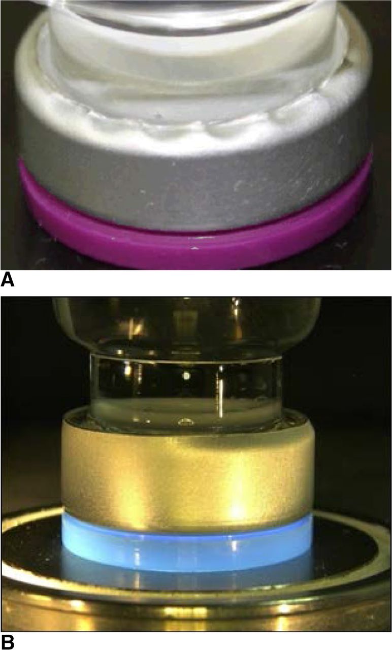
Defects associated with rubber stopper compression: (A) Wrinkled crimp cap skirt (too high rubber stopper compression), (B) Partially crimped vial (too low rubber stopper compression).
In this study, we used different CSS configurations from different GMP DP fill & finish facilities to investigate the influence of vial size and rubber stopper design on the capping process. In addition, we compared two examples of large-scale GMP manufacturing capping equipment and different capping equipment settings to assess their influence on product quality and integrity, measuring residual seal force. The RSF results of the GMP capping equipment was compared to the capping process of a piece of lab-scale capping equipment used in a previous study (7) to investigate differences of a lab-scale and GMP manufacturing-scale capping process. The sealed vials were analyzed using a RSF tester, CT, and a helium leak mass spectrometer (pCCI) as described previously (7).
Materials and Methods
Vials, Rubber Stoppers, Crimp Caps
Type I glass vials (6 mL, 15 mL, and 20 mL), (Schott AG, Mainz, Germany), all with 20 mm vial heads, were sealed using a Daikyo (Tokyo, Japan) D777-1 serum or lyophilization (lyo) rubber stopper featuring similar rubber stopper flange heights (serum rubber stopper had a flange height of 2.97 mm; the lyo rubber stopper had a flange height of 3.06 mm). The Daikyo rubber stoppers feature a proprietary coating at the product contacting side; however, the rubber stopper sealing area is essentially free of coating. All vials were sealed using a Datwyler (Altdorf, Switzerland) crimp cap.
GMP-scale Capping Equipment
Vials were sealed with Bausch & Stroebel (Ilshofen, Germany) GMP manufacturing capping equipment RVB4090. The Bausch & Stroebel RVB4090 can produce 24,000 vials/hour and the capping head (carousel) features 16 stations, each station with an individual turntable, plunger, and capping plate. The capping equipment process parameters were chosen as follows: The capping pre-compression force was set to minimum force, target value, and maximum force. The turntable rotation speed was also investigated, from minimum speed, to target value speed, and maximum speed. The capping plate to plunger distance was investigated at maximum manufacturing operating ranges, that is, in the broadest process range operated at our commercial sites (any further change in capping plate to plunger distance would require significant conversion of the capping equipment).
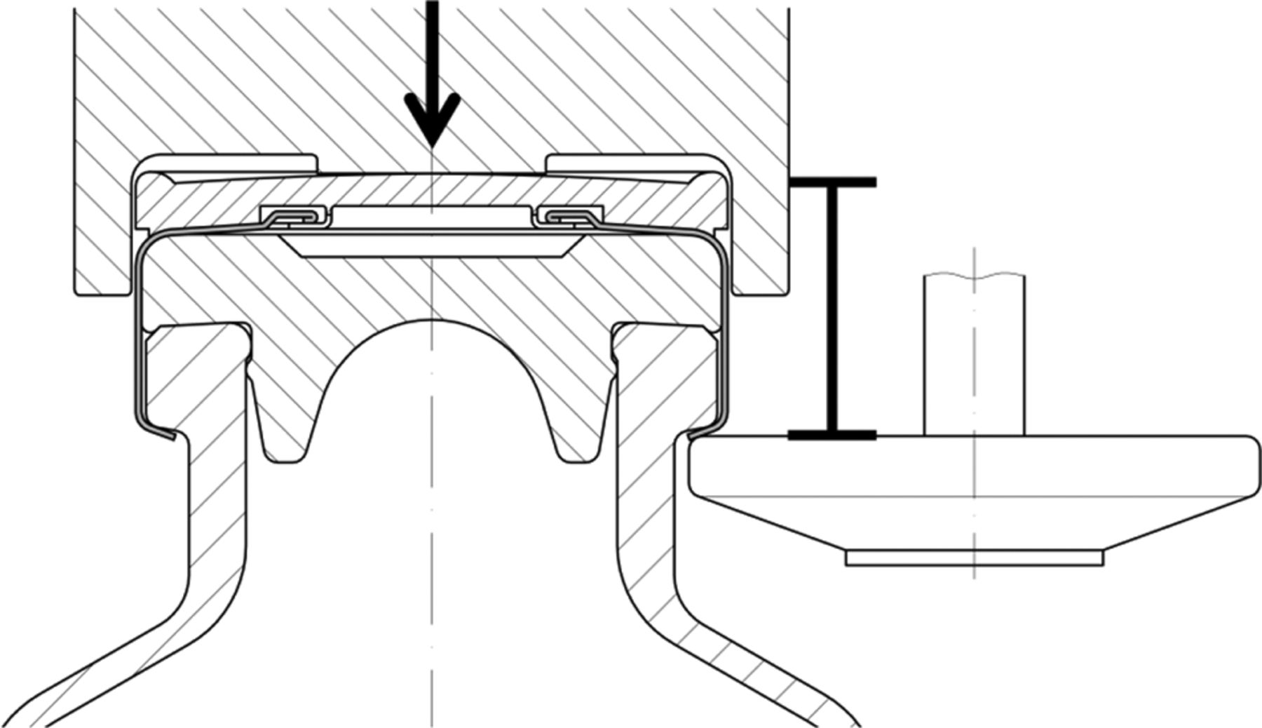
The capping plate-plunger distance (Figure 2, caliper) was set to 7.5 mm. The distance was adjusted by differently sized shim rings, which increase the distance of the capping plate to plunger distance. The total capping plate-plunger distance (always noted in all graphs) was the sum of 7.5 mm and the height of the used shim ring. The capping pre-compression forces (Figure 2, arrow) was set from 3.4 bar up to 5.8 bar. The rotation speeds of the turntables were changed from 108 rpm up to 774 rpm. Negative values indicate counterclockwise rotation of the turntable whereas positive values indicate clockwise rotation of the turntable.

The capping process: capping plate to plunger distance (caliper), capping pre-compression force (arrow).
In addition to the capping equipment by Bausch & Stroebel, vials were also sealed using Groninger KVK 306B (Crailsheim, Germany) capping equipment (Figure 3). The Groninger KVK 306B can produce 7200 vials/h and the capping head features 6 stations with an individual turntable and plunger. The Groninger capping equipment has one big capping plate in the middle of the capping station. The distance of the plunger to the capping plate was fixed to 7.9 mm (similar to the setting of the Bausch & Stoebel capping equipment). The rotation speed was kept at comparable levels for each vial format during the capping process.
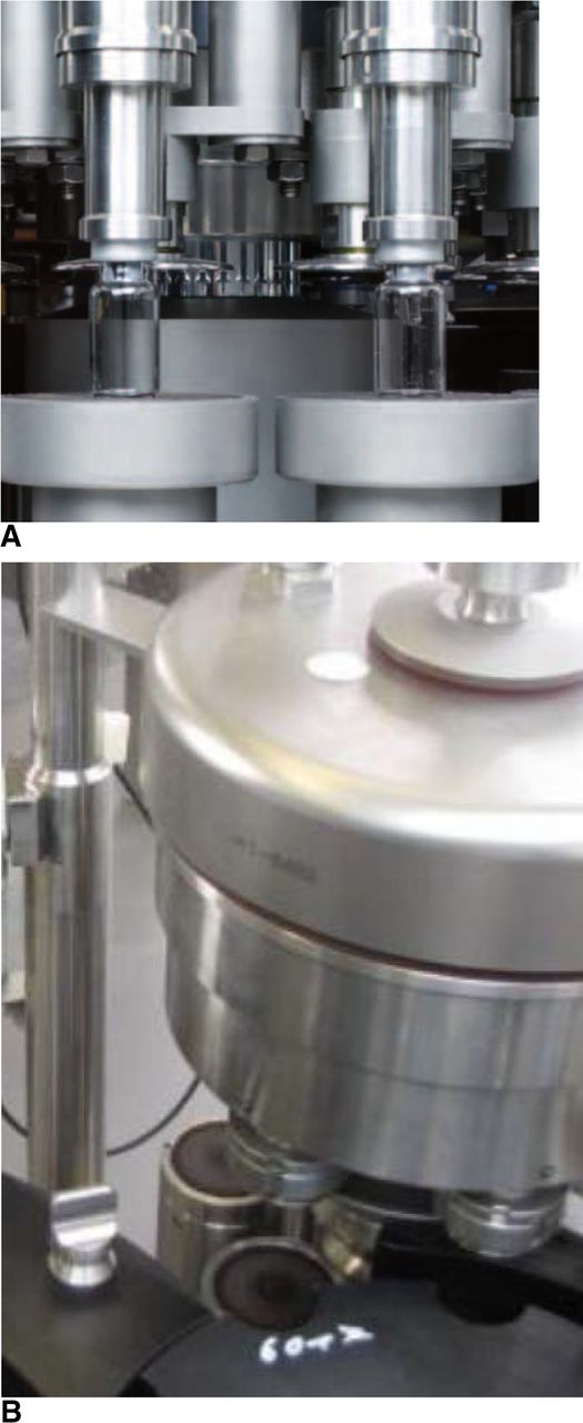
The (A) Bausch & Stroebel RVB4090 capping equipment and (B) Groninger KVK306B capping equipment.
RSF
The Genesis Packaging Technologies (Exton, PA, USA) RSF tester was used to measure the GMP sealed vials. The RSF tester's measuring principle was described elsewhere in great detail (6, 8⇓–10). All GMP-sealed vials featured the same crimp cap. Therefore, the same cap anvil could be used to measure all samples. Prior to the RSF measurement the flip-off button was removed to increase RSF accuracy (7). Thirty samples were measured per group. All samples were measured on comparable time points after the capping process. Samples were analyzed between days 2 and 7 after the capping process, to ensure reliable and comparable RSF measurements. Each measurement contained 3 sub-runs.
CT
The microCT system exaCT (Wenzel, Volumetric GmbH, Singen, Germany) was used to measure the sealed vials from GMP drug product manufacturing. The power source voltage was set to 95 V, the amperage to 2.5 mA, and quick measuring time was used with high resolution. The reconstruction of 3D images and image analyzing was performed with the exaCT control software 2.0 (Wenzel, Volumetric GmbH, Singen, Germany). The rubber stopper flange height was measured at 4 points to identify asymmetrically capped vials. The rubber stopper compression was calculated by the difference of the rubber stopper flange before the capping process and after the capping process. CT measurements demand time and complex image analysis. Therefore, only one vial per group could be measured.
Mass Spectroscopy-based Helium Leak Measurements
An ASM340 mass spectrometric helium leak detector (Pfeifer Vacuum, Asslar, Germany) was used to perform Helium leak measurements as described previously (11). In brief, a sealed test vial was cut open at the bottom with a diamond blade. Then it was placed in an in-house manufactured airtight flange, connecting the test vial and the helium leak detector. The vacuum pump was turned on and helium gas was applied on the outside of the vial. In this test setup the only path of the helium gas (applied at the outside of the vial) to the detector is through a leak at the vial sealing area or glass cracks at the vial head shoulder. CCI failure was assumed at a helium leak rate of above 10−7 mbar L/s. Any vial with a helium leak rate equal or below 10−7mbar L/s was considered as microorganism tight. For time reasons, measurements were stopped at a helium leak rate of 10−8 mbar L/s, which would also be considered gas tight, although the leak rate of a sufficiently sealed vial would eventually usually reach leak rates below 10−12 mbar L/s, which is the lower detection limit of the mass spectrometric detector 30 vials per group were measured.
Statistical Analysis
Statistical analysis was performed with Microsoft Excel 2010. A one-way analysis of variance (ANOVA) followed by a post-hoc Student t-test was performed. The P-value was set to <0.001.
Results
RSF Measurements
The influence of a single process parameter on the RSF of the sealed vial was investigated with a univariate change study design. Therefore, one process parameter was changed from low to high values, whereas all the other process parameters were kept constant. In addition two GMP manufacturing (7) capping equipment and three different CCS configurations were tested to investigate:
The influence of the capping plate-plunger distance
The influence of the capping pre-compression force
The influence of the rotation speed of the turntable
The influence of the CCS configuration
The influence of the capping equipment
on the RSF of a sealed vial.
1. The Influence of the Capping Plate to Plunger Distance
The 6 mL vials with serum rubber stoppers were sealed with 3 different capping plate to plunger distances, the 15 mL vial with lyo rubber stoppers were sealed with two different capping plate to plunger distances.
The 6 mL vials with serum rubber stoppers were all sealed with 4.0 bar capping pre-compression force and –183 rpm turntable rotation speed. The distance of the plunger to the capping plate had a major and significant influence on RSF (Figure 4A). A small distance led to high RSF values, whereas a larger distance resulted in low RSF values. Vials sealed with a capping plate to plunger distance of 7.7 mm (Figure 4A, white bar) showed 71.1 ± 6.7 N RSF, and a capping plate to plunger distance of 8.1 mm showed RSF values of 48.9 ± 5.4 N. In contrast, a distance of 8.4 mm resulted in only 31.6 ± 4.6 N.

RSF measurement of vials sealed with different capping plate to plunger distances: (A) 6 mL vial, D777 serum rubber stopper, Bausch & Stroebel capping equipment; (B) 15 mL vial, D777 lyo rubber stopper, Bausch & Stroebel capping equipment.
The 15 mL vials with lyo rubber stoppers were all sealed with 4.8 bar capping pre-compression force and −136 rpm turntable rotation speed. Similar results were observed for the 15 mL vials.
The distance of the capping plate to the plunger had a major influence on measured RSF values (Figure 4B); interestingly the RSF values measured were similar to the 6 mL vials with an identical capping plate to plunger distance though the pre-compression force and the turntable speed were slightly different. A capping plate to plunger distance of 8.1 mm resulted in a RSF value of 52.8 ± 7.5 N, whereas the smaller capping plate to plunger distance of 7.7 mm lead to an RSF value of 75.1 ± 9.2 N. 15 mL vials with a capping plate to plunger distance of 8.4 mm were not investigated.
The capping plate applies an additional force upwards, which further compresses the rubber stopper. Rubber stopper compression was directly linked to RSF as shown in our previous study (7). A short distance between the plunger and the capping plate leads to a large force vector from below, higher rubber stopper compression and therefore to higher RSF values.
2. The Influence of the Capping Pre-compression Force
The 6 mL vials with serum rubber stoppers and the 15 mL vials with lyo rubber stoppers were sealed with 3 different capping pre-compression forces (covering the range from min to max capping pre-compression force of the Bausch & Stroebel capping equipment).
For the 6 mL vials with serum rubber stoppers, the capping pre-compression force (pressure in the pneumatic cylinder) had only a minor influence on the resulting RSF values (Figure 5A) compared to the capping plate to plunger distance. Although a statistically significant difference in RSF could be measured between 3.4 bar and 4.0 bar/5.8 bar, the difference in absolute numbers was low. The lowest capping pre-compression force (3.4 bar) resulted in 42.5 ± 4.4 N. The highest pressure resulted in 51.4 ± 7.9 N.
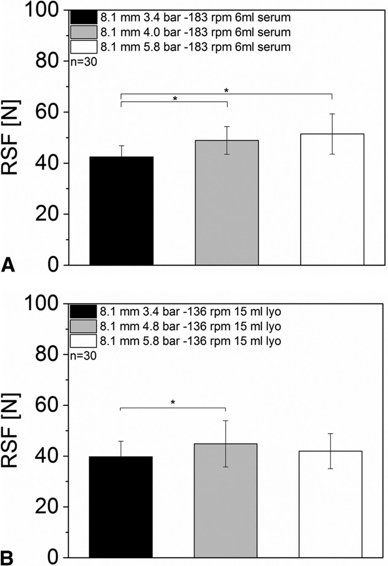
RSF measurements of vials sealed with different capping pre-compression forces: (A) 6 mL vial, D777 serum rubber stopper, Bausch & Stroebel capping equipment; (B) 15 mL vial, D777 lyo rubber stopper, Bausch & Stroebel capping equipment.
Again, for the 15 mL vials with lyo rubber stoppers, no trend was observed for the different capping pre-compression forces (Figure 5B). All groups showed RSF values between 39.7 ± 6.1 and 44.8 ± 9.1 N.
The capping pre-compression force can be derived from pressure parameters of the pneumatic cylinder or a stress-strain gauge. However, the capping pre-compression force showed only a minor influence on the measured RSF value of a sealed DP unit. In contrast, the additional force applied by the capping plate, which greatly influences RSF, cannot be measured. These results highlight the need for an analytical method which measures the final resulting RSF of a sealed vial.
3. The influence of the Rotation Speed of the Turntable
The 6 mL vials with serum rubber stoppers and the 15 mL vials with lyo rubber stoppers were sealed using 5 different turntable rotation speeds and a constant capping plate to plunger distance and capping pre-compression force.
A change in the rotation speed of the turntables, which rotate the vial during the capping process, showed only a minor influence on the measured RSF values (Figure 6). All sample groups of the 6 mL vials with serum rubber stoppers and different rotation speeds showed RSF values between 47.39 ± 6.6 N and 51.33 ± 8.3 N. No statistically significant difference between the sampled groups was observed (Figure 6A).
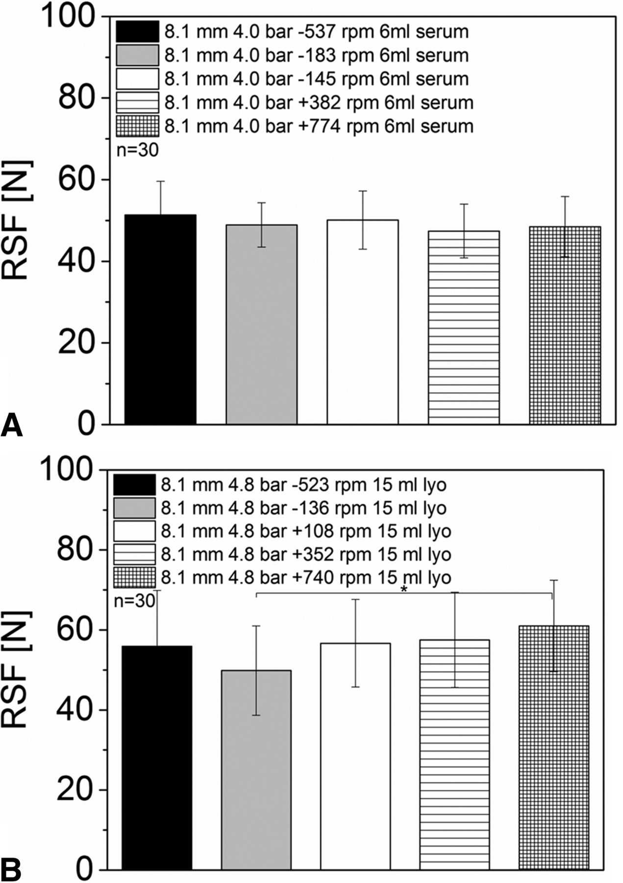
RSF measurements for vials sealed with different turntable rotation speeds: (A) 6 mL vials, D777 serum rubber stopper, Bausch & Stroebel capping equipment; (B) 15 mL vials, D777 lyo rubber stopper, Bausch & Stroebel capping equipment.
Similar RSF results were obtained for the 15 mL vials with lyo rubber stoppers. No major differences or trends between the different sample groups were found (RSF values from 49.9 ± 11.2 N and 61.0 ± 11.4) (Figure 6B).
A comparison of GMP-scale capping equipment to lab-scale capping equipment investigating the rotation speed of the turntables is challenging as they usually feature different designs. Therefore, studies using the actually capping equipment is generally recommended (6,7).
The horizontal rotation speed during the capping process was not expected to influence the vertical force vectors applied on the CCS during the capping process, which compress the rubber stopper. Nevertheless, the rotation speed of the turntable is an important capping process design parameter to eliminate cosmetic defects; for example, a fast rotation speed may smooth small wrinkles of the crimp cap under the vial flange.
4. Impact of the CCS on the RSF
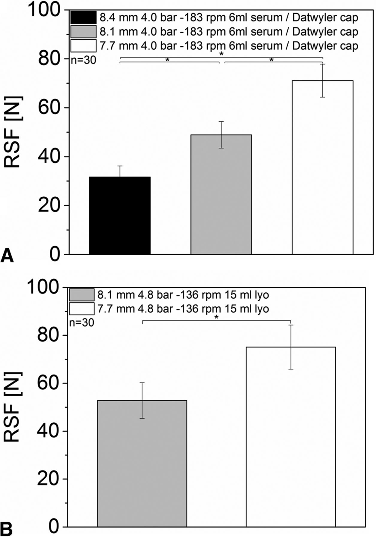
Six milliliter vials with serum rubber stoppers, 15 mL vials with lyo rubber stoppers, and 20 mL vials with lyo rubber stoppers were all sealed with a Datwyler crimp cap and the Bausch & Stroebel RVB4090 capping equipment. During a format change, the total capping head height of the capping equipment is adjusted to the new vial height. The capping plate to plunger distance only needs to be changed if vials with a different vial head are sealed. In our case all vials featured the same vial head but different vial heights. The plate height was identical for all formats; the capping pre-compression force and the rotation speed of the turntables were in similar ranges.
All formats showed comparable RSF values (between 48.1 ± 9.2 N up and 52.8 ± 7.5 N, Figure 7). The vial size (vial height) or the rubber stopper design only showed a minor influence on RSF.

RSF measurements for different vial formats sealed with the same capping process parameters.
5. Impact of the Capping Equipment on the RSF
The same vial formats (6 mL vials with serum rubber stoppers, 15 mL vials with lyo rubber stoppers, and 20 mL vials with lyo rubber stoppers (all with Datwyler crimp cap)) were also sealed using the Groninger KVK306 B capping equipment. The capping plate to plunger distance had similar settings compared to the Bausch & Stroebel capping equipment. However, the capping pre-compression force is measured in Newton with the Groninger capping equipment (compared to bar with the Bausch & Stroebel RVB 4090), the capping plate has a different shape, and the capping equipment was running at a higher overall output speed.
The overall RSF values for the vials sealed with the Groninger capping equipment were generally slightly lower compared to the Bausch & Stroebel sealed vials (Groniger RSF values were lower with similar capping plate to plunger distance). The 6 mL vials with serum rubber stoppers showed RSF values of 31.1 ± 2.8 N. The 15 mL vials with lyo rubber stoppers and 20 mL vials with lyo rubber stoppers displayed RSF values between 37.8 ± 2.9 N and 45.5 ± 4.0 N (Figure 8). In contrast to the Bausch & Stroebel capping equipment, the different formats showed different RSF values with the Groninger capping equipment.

RSF measurements of different formats sealed with a Groninger capping equipment.
In a previous study with Integra West lab-scale capping equipment, we sealed 15 mL vials featuring the same vial head with the same serum rubber stopper and the Datwyler crimp cap. The capping pre-compression force was set to 44.48 N and the capping plate to plunger distance was set to 8.48 mm. The resulting RSF values of 39.8 ± 4.3 N were much higher than RSF values from GMP manufacturing capping equipment with similar process parameters (7). This can be explained by having closed the vials with an overall different capping process with spinning rollers. In conclusion, the RSF after capping is highly dependent on the capping equipment used. It can be expected that similar capping process settings used on capping equipment from different manufacturers likely lead to different RSF values.
CT
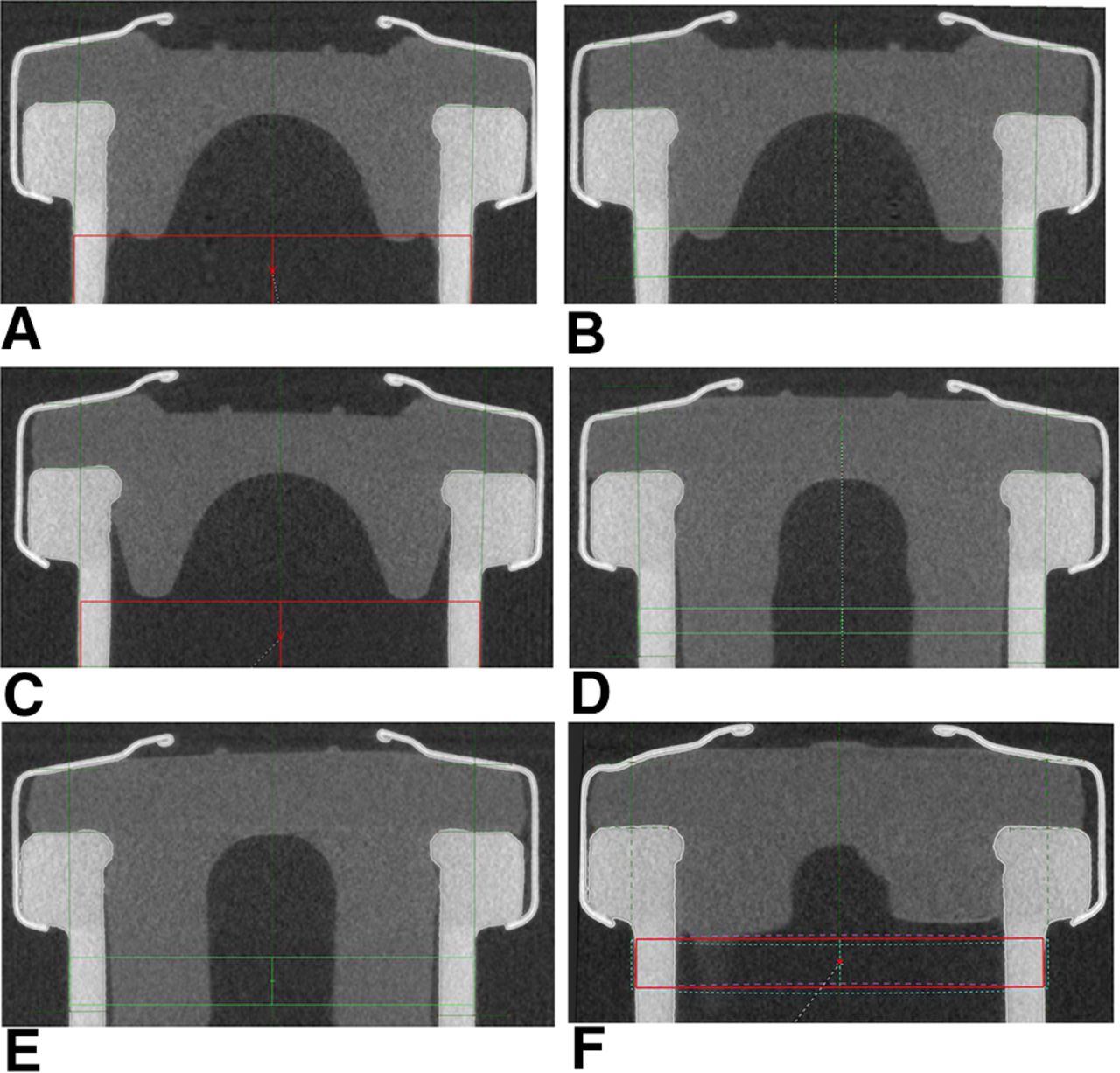
All samples were also characterized with CT to measure the rubber stopper compression of the sealed vials and to check for rubber stopper defects, for example, deformation, dimpling, and ruptures (Figure 9).

CT images of 6 mL serum vials and 15 mL lyo vials: (A) 6 mL vial (highest measured RSF, 71.0 ± 6.7 N), D777 serum rubber stopper, Bausch & Stroebel capping equipment; (B) 6 mL vial (lowest measured RSF, 31.6 ± 4.5 N), D777 serum rubber stopper, Bausch & Stroebel capping equipment; (C) 6 mL vial (RSF, 31.1 ± 2.8 N), D777 serum rubber stopper, Groninger capping equipment; (D) 15 mL vial (highest measured RSF, 75.1 ± 9.2 N), D777 serum rubber stopper, Bausch & Stroebel capping equipment; (E) 15 mL vial (lowest measured RSF, 39.7 ± 6.1 N), D777 serum rubber stopper, Bausch & Stroebel capping equipment; (F) 15 mL vial (RSF, 37.7 ± 2.9 N), D777 serum rubber stopper, Groninger capping equipment.
None of the sealed vials showed any defects within the RSF range investigated in this study. In a previous study no glass or rubber stopper defects could be observed for the same CCSs with even higher RSF values (up to 110 N). None of our capping equipment could bring that specific CCS to the edge of failure. However, we also observed that CCS defects are highly dependent on the CCS configuration. Small vials featuring a small vial head showed rubber stopper deformation (dimpling) at RSF values >100 N (7). Also, any value outside the RSF range tested may also possibly lead to critical defects. Of note, the assessment of RSF range and CCI is required to be undertaken for each CCS and capping process specifically.
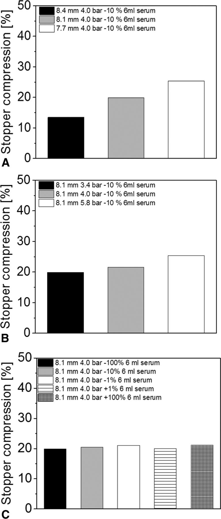
Rubber stopper compression measured by CT showed similar trends to RSF measurements: CCSs with the highest RSF values showed the highest rubber stopper compression, whereas the CCSs with the lowest RSF values showed the lowest rubber stopper compression. For example, the CCSs sealed with the smallest capping plate to plunger distance displayed RSF values of 71.0 ± 6.7 N and a rubber stopper compression of 25.9%. In contrast, the vials with the largest capping plate to plunger distance showed the lowest RSF values (31.6 ± 4.5 N) and the lowest rubber stopper compression (13.5%) (Figure 10A).

Rubber stopper compression of 6 mL vials with a D777 serum rubber stopper, sealed with the Bausch & Stroebel capping equipment, measured by CT: (A) Different capping plate to plunger distances, (B) Different capping pre-compression forces, (C) Different turntable rotation speeds.
The capping pre-compression force had only a minor effect on rubber stopper compression. All vials had a rubber stopper compression between 19.9% and 25.4% (Figure 10B). In addition, the turntable rotation speed only had a minor effect on rubber stopper compression. All measured sample groups showed a rubber stopper compression between 18.9% and 21.1% (Figure 10C).
No vials showed any defects. The rubber stopper compression was a function of RSF (high RSF resulted in high rubber stopper compression, whereas low RSF resulted in low rubber stopper compression). In our previous study (7) as well as those of Morton et al. (5, 10, 12) observed a similar correlation between RSF and rubber stopper compression.
In conclusion, rubber stopper compression is an important design parameter of the capping process and correlated to RSF. A high rubber stopper compression leads to a long crimp cap skirt folded under the vial flange, which can possibly lead to wrinkles. In contrast, a low rubber stopper compression may lead to a too short crimp cap skirt folded under the vial flange, which can result in partially sealed vials, although we have not observed this phenomenon in our study.
In our study all vials had adequate rubber stopper compressions as no CCS showed any visual defects such as wrinkles of the crimp cap skirt or partially crimped vials.
Mass Spectroscopy–based Helium Leak Measurements
All groups were analyzed with a mass spectrometry-based helium leak system to investigate the impact of the capping process on CCI (Table 1).
CCI Measurements (Helium Leak Rates) of Different Vial Formats Sealed with Bausch & Stroebel or Groninger Capping Equipment
No vial showed any helium leakage (including the vials with the highest and lowest RSF values). CCI was ensured over a broad range of RSF, so far investigated from 31.1 ± 2.8 N up to 75.1 ± 9.2 N.
Similar results were obtained in a previous study with lab-scale capping equipment, where no vials (RSF range from 10 up to 120 N) showed any leakage (7).
The correlation of RSF range and CCI, however, are suggested to be performed for each individual CCS configuration or at least to apply a bracketing of a worst case concept (e.g., test CCS with lowest and highest RSF values for CCI). It is considerable that a lower quality of glass vials with imperfections on the vial sealing area or rubber stoppers with lower elasticity might require a certain level of RSF to be sealed.
Conclusion
In this study, different CCSs configurations were sealed with two examples of large-scale manufacturing capping equipment and a variety of different capping process parameters. The capping plate to plunger distance had the strongest influence on the RSF of a sealed vial, whereas the capping pre-compression force and the turntable rotation speed only had a minor influence on the RSF. CT confirmed that in the investigated RSF range no vials showed any rubber stopper deformation or ruptures and rubber stopper compression was a function of RSF. All vials passed CCI testing with helium leakage.
The measured process parameters such as the capping pre-compression force or capping plate height do not adequately describe the final capping result. The RSF tester can be used to characterize the resulting residual seal force of a capped vial independent of the used capping equipment, which can facilitate the comparison of the seal quality of DP units manufactured in different DP facilities. In addition, a suitable RSF range, that would still show full CCI, is recommended specific for each CCS combination and can be established using different capping equipment.
Conflict of Interest Declaration
The authors declare that they have no competing interests.
Footnotes
At the author's request, this version of the article contains a correction added on July 19, 2016: Page 113, first paragraph, line 20: the value originally posted as “10−2” has now been corrected to “10−12”.
Abbreviations:
- CCI
- Container closure integrity
- CCS
- Container closure system
- CT
- Computer tomography
- DP
- Drug product
- GMP
- Good manufacturing practice
- Lyo
- Lyophilization
- N
- Newton
- pCCI
- physical CCI
- RPM
- Rounds per minute
- RSF
- Residual seal force
- © PDA, Inc. 2016


Jump to section
Related Articles
Cited By...
- Use of a Predictive Regression Model for Estimating Hold-Up Volume for Biologic Drug Product Presentations
- Quantifying the Vial-Capping Process: Reexamination Using Micro-Computed Tomography
- Long-Term Study of Container Closure Integrity of Rubber-Glass Vial Systems by Multiple Methods
- Balancing Container Closure Integrity and Aesthetics for a Robust Aseptic or Sterile Vial Packaging System
- Residual Seal Force Testing: A Suitable Method for Seal Quality Determination of (High Potent) Parenterals
- Evaluation of Container Closure System Integrity for Storage of Frozen Drug Products: Impact of Capping Force and Transportation
- Sealing Behaviour of Container Closure Systems under Frozen Storage Conditions: Nonlinear Finite Element Simulation of Serum Rubber Stoppers
- Holistic Considerations in Optimizing a Sterile Product Package to Ensure Container Closure Integrity