
Abstract
The majority of parenteral drug products are manufactured in glass vials with an elastomeric rubber stopper and a crimp cap. The vial sealing process is a critical process step during fill-and-finish operations, as it defines the seal quality of the final product. Different critical capping process parameters can affect rubber stopper defects, rubber stopper compression, container closure integrity, and also crimp cap quality. A sufficiently high force to remove the flip-off button prior to usage is required to ensure quality of the drug product unit by the flip-off button during storage, transportation, and until opening and use. Therefore, the final product is 100% visually inspected for lose or defective crimp caps, which is subjective as well as time- and labor-intensive. In this study, we sealed several container closure system configurations with different capping equipment settings (with corresponding residual seal force values) to investigate the torque moment required to turn the crimp cap. A correlation between torque moment and residual seal force has been established. The torque moment was found to be influenced by several parameters, including diameter of the vial head, type of rubber stopper (serum or lyophilized) and type of crimp cap (West® or Datwyler®). In addition, we measured the force required to remove the flip-off button of a sealed container closure system. The capping process had no influence on measured forces; however, it was possible to detect partially crimped vials. In conclusion, a controlled capping process with a defined target residual seal force range leads to a tight crimp cap on a sealed container closure system and can ensure product quality.
LAY ABSTRACT: The majority of parenteral drug products are manufactured in a glass vials with an elastomeric rubber stopper and a crimp cap. The vial sealing process is a critical process step during fill-and-finish operations, as it defines the seal quality of the final product. An adequate force to remove the flip-off button prior to usage is required to ensure product quality during storage and transportation until use. In addition, the complete crimp cap needs to be fixed in a tight position on the vial. In this study, we investigated the torque moment required to turn the crimp cap and the force required to remove the flip-off button of container closure system sealed with different capping equipment process parameters (having different residual seal force values).
- Residual seal force (RSF)
- Container closure system (CCS)
- Capping
- Crimping
- Crimp cap
- Flip-off removal
- Torque moment
- Process control
Introduction
The container closure system (CCS) for parenteral drug products must fulfill several requirements (1, 2), for example, containment, protection (3), and sterility (4). CCSs are designed and qualified prior to use for an actual product and administration to humans to ensure microbiological quality (sterility) during manufacturing in connection with environmental controls and other good manufacturing practice (GMP) elements, as well as over the duration of shelf-life (container closure integrity, CCI). Any microbial contamination of the drug product can cause critical side effects in patients. Today the majority of parenteral drug products are manufactured in glass vials with an elastomeric rubber stopper and a crimp cap, followed by pre-fillable syringes (1).
Obviously, the vial sealing process is a critical process step during fill-and-finish operations, as it defines the seal quality of the final product (5⇓–7). The vial sealing process comprises several steps: After stoppering, a crimp cap is placed on the rubber stopper, then the crimp cap/rubber stopper/glass vial combination is compressed and the cap skirt of the crimp cap is folded under the vial flange, fixing the rubber stopper in its compressed position, which effectively seals the vial. GMP manufacturing capping equipment needs to be qualified and the capping process needs to be adequately controlled. Lately, the capping process has received increasing attention by authorities, for example, USP <1207> has been revised: The current draft of USP <1207> now features an individual section <1207.3> describing methods to monitor the vial sealing process (8).
The residual seal force (RSF) tester is an adequate method to characterize capping equipment and to monitor the vial-sealing process independent of the used capping equipment and CCS configuration (9⇓⇓⇓–13). The influence of different critical capping process parameters on rubber stopper defects, rubber stopper compression, and CCI was described in a previous study (9). However, the influence of the capping process on the crimp cap is in general insufficiently studied.
The flip-off button protects the rubber stopper of the CCS, which will be penetrated by the needle to withdraw product solution prior injection. A sufficiently high force to remove the flip-off button prior to usage is required to ensure the cap remains in place during storage, shipping, manufacturing, and handling; however, a sufficiently low force is required to ensure usability, that is, the capability of the user to remove the cap prior product withdrawal. The capping process might influence the force required to remove the flip-off button. High capping pre-compression forces might break the plastic fingers or the pre-cut metal bridges connecting the flip-off button and the metal part of the crimp cap. In addition, lyophilized (lyo) rubber stoppers can bulk up upon excessive capping forces and could potentially pop off the flip-off button.
During GMP manufacturing the final product is checked 100% visually for various defects, including loose crimp caps and other crimp cap defects. When performed manually, the visual inspection operator tries to turn the crimp cap of the sealed vial by hand. This test setup is time-consuming and, despite extensive training and operator qualification, somewhat subjective (14).
In this study, we aimed to investigate the relation of various capping process parameters and flip-off cap removal force as well as the torque moment required to turn the crimp cap on a sealed vial. We sealed a variety of CCS configurations with laboratory-scale and commercial-scale capping equipment with different capping equipment settings and analyzed the torque moment required to turn the crimp cap on the sealed CCS. The torque moment to turn the crimp cap was correlated to the corresponding RSF values of the tested CCS. In addition, we analyzed the force required to remove the flip-off button of the sealed CCS. The integrity of the connection of the flip-off button and the metal part of the crimp cap was also investigated by using computed tomography (CT) images.
Materials and Methods
Glass Vials, Rubber Stoppers, and Crimp Caps
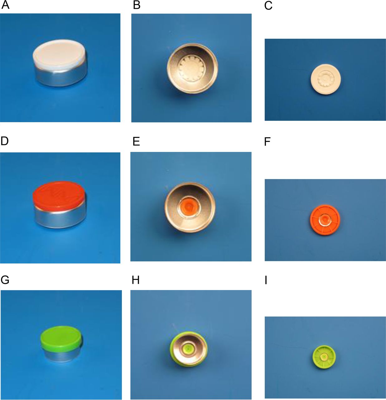
The 3 mL vials featured a small vial head (13 mm outer diameter). The 6 mL and 15 mL vials featured a large vial head (20 mm outer diameter) (Schott AG, Mainz, Germany). All vials were of type I glass quality. The different vial formats were sealed using corresponding Daikyo (Tokyo, Japan) D777-1 serum or lyo rubber stoppers and Datwyler (Altdorf, Switzerland) (Figure 1A–C) or West (Exton, PA, USA) (Figure 1D–I) crimp caps. The Datwyler and West crimp caps featured different designs of the connection between the flip-off button and the crimp cap. The 20 mm Datwyler crimp cap has plastic fingers (Figure 1B) to keep the flip-off button on the metal part of the crimp cap prior to usage, whereas the 13 mm and 20 mm West crimp cap has pre-cut metal bridges (Figure 1E,H; Figure 11).

Used crimp caps: A, B, C: 20 mm Datwyler crimp cap for 6 mL and 15 mL vials with plastic fingers connecting the flush flip-off button to the metal part. D, E, F: 20 mm West crimp cap for 6 mL and 15 mL vials with pre-cut bridges connecting the flush flip-off button to the metal part. G, H, I: 13 mm West crimp cap for 3 mL vials with pre-cut bridges connecting the overhanging flip-off button to the metal part.
Laboratory-Scale Vial Capping
An Integra West Capper (Genesis Packaging Technologies, Exton, PA, USA) was utilized to seal the different CCS configurations.
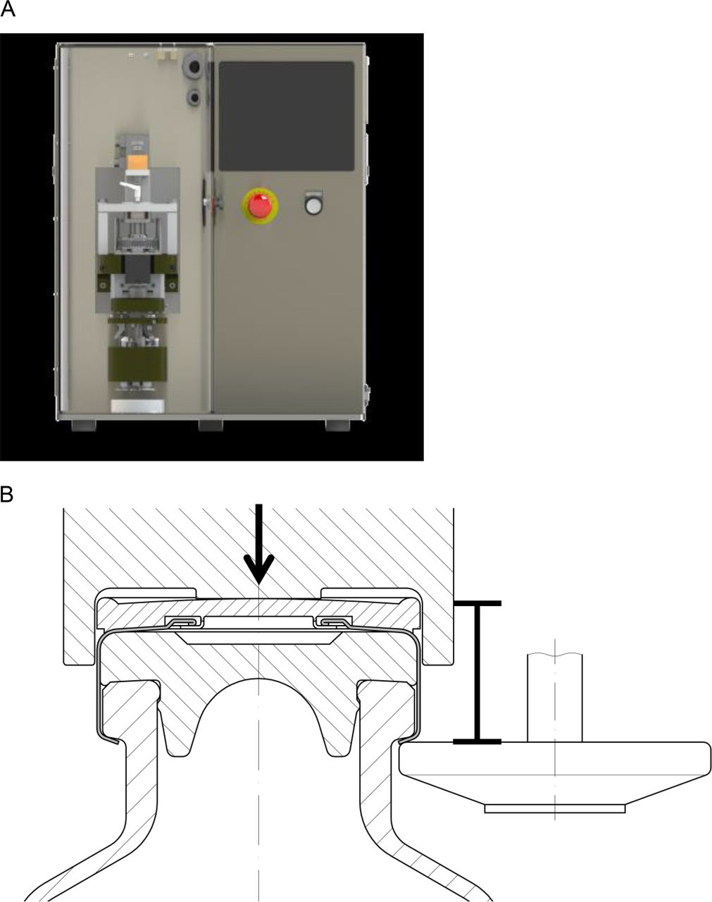
The capping pre-compression force (Figure 2B, arrow) as well as the capping plate-to-plunger distance (distance between plunger and capping plate, Figure 2B, caliper) were modified to analyze the influence of capping process parameters on the crimp cap. The used capping equipment settings are detailed in Table I.

(A) Used laboratory-scale capping equipment by Genesis Packaging Technologies, (B) Vial capping process: Caliper = distance capping plate – plunger, arrow = pre-compression force.
Overview of the Capping Equipment Settings Used in This Study
Commercial-Scale Vial Capping
A Bausch&Stroebel (Ilshofen, Germany) commercial-scale capping equipment RVB4090 (Figure 3) was used to seal 6 mL vials featuring the same vial head, rubber stopper, and crimp caps as the 15 mL vials used in the laboratory-scale experiment. The Bausch&Stroebel RVB4090 commercial-scale capping equipment features a capping head (carousel) with 16 stations, each station with an individual plunger and capping plate. The capping plate-to-plunger distance (Figure 2B, caliper) was set to 7.5 mm and was further adjusted by differently sized shim rings, which increase the capping plate-to-plunger distance to its final value. Three final capping plate-to-plunger distances (7.7 mm, 8.1 mm, and 8.4 mm) in combination with 4.0 bar capping pre-compression pressure were used to manufacture vials with different RSF values.

Bausch&Stroebel RVB4090 commercial-scale capping equipment.
RSF Measurements
The RSF tester by Genesis Packaging Technologies was utilized to analyze the different CCS configurations sealed with the different capping equipment settings. Three cap anvils were produced in-house to fit the 20 mm Datwyler and West crimp caps and the 13 mm West crimp cap, respectively. All RSF measurements were performed without a flip-off button for increased accuracy of the test (9). Each sample group contained 20 vials. The RSF value of a sample group was obtained by averaging the 20 measurements.
CT Measurements
The connection of the flip-off button and the metal part of the crimp cap of different CCS configurations were analyzed with a micro CT system, exactCT (Wenzel, Volumetric GmbH, Singen, Germany). CT settings were optimized in a previous study (9). The measurements were performed with high resolution; the measuring time was set to quick and power settings to 95 V/2.5 mA. The exactCT control software 2.0 (Wenzel, Volumetric GmbH) was utilized for data analysis. CT measurements are labor-intensive and demand complex 3D image reconstruction and analysis. Therefore, only one CCS per sample group was measured, which makes this method impractical for the routine use in research and development or quality control.
Torque Moment Measurements
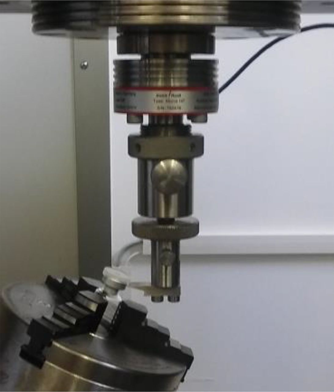
An Orbis Mecmesin (Slinfold, UK) digital torque tester was used to analyze the torque moment required to turn the crimp cap of a sealed vial. A test vial was fixed in the torque tester (Figure 4), and the crimp cap was turned slowly by hand. The recorded maximum torque moment corresponds to the break-lose torque moment required to turn the crimp cap on a sealed CCS. Each sample group contained 20 vials. The torque moment of a sample group was calculated by averaging the 20 measurements.

Orbis Mecmesin (Slinfold, UK) digital torque tester with a 6 mL vial.
Flip-Off Button Removal Force Measurements
The force required to remove the flip-off button was measured with a Zwick/Roell (Ulm, Germany) Z020 stress strain tester modified by an in-house build device (Figure 5). The test setup was according to DIN EN ISO 8362-7:2011-03. In brief, the vial was fixed in a lathe chuck in a 23 degree angle to the push rod. The push rod speed was set to 100 mm/min. The force maximum of the force distance plot was set as the force required to remove the flip-off button.

Zwick/Roell Z020 stress strain tester with the in-house build flip-off button removal setup.
Results and Discussion
The CCS configurations were sealed using laboratory-scale and a commercial-scale capping equipment with different capping equipment process parameters (with different corresponding RSF values) to analyze the influence of
the RSF
the rubber stopper design (serum vs lyo)
the crimp cap design (plastic finger connectors vs pre-cut metal bridges)
the rubber stopper size
the capping equipment (laboratory scale vs commercial scale)
on the torque moment required to turn the crimp cap and the force required to remove the flip-off button of a sealed vial.
Laboratory-Scale Experiments
RSF:
The 3 mL vials were sealed using six different capping equipment settings, and the 15 mL vials were sealed using five different capping equipment settings.
The six capping equipment settings generated 3 mL CCSs with RSF values ranging from 13.8 ± 2.2 N to 98.4 ± 7.0 N (Table II). The five capping equipment settings generated 15 mL CCSs with RSF values ranging from 9.8 ± 1.6 N to 105.6 ± 8.6 N (Table II). The CCS configuration (serum vs lyo rubber stopper and Datwyler vs West crimp cap) showed only a minor influence on the obtained RSF values. At a given capping equipment setting, the different CCS configurations featured comparable RSF values (Table II). Similar results were observed in a previous study with different CCS configuration (9). Therefore, any difference in torque moment or force required to remove the flip-off button between the different CCS configuration sample groups can be attributed to the packaging components and not to differences in RSF.
RSF (N) of the Different CCS Configurations from Capping Equipment Setting 1 to 6. At Capping Equipment Setting 1 the RSF of the 3 mL Vials was Below the Detection Limit (error)
Torque Moment Measurements:
The CCS configuration as well as the RSF influenced the torque moment required to turn the crimp cap of a sealed vial.
The Influence of the RSF on the Torque Moment Required to Turn the Crimp Cap:
The RSF had a major influence on the torque moment. CCSs with increasing RSF values required linearly increasing torque moments to turn the crimp cap of a sealed vial (Figure 6).

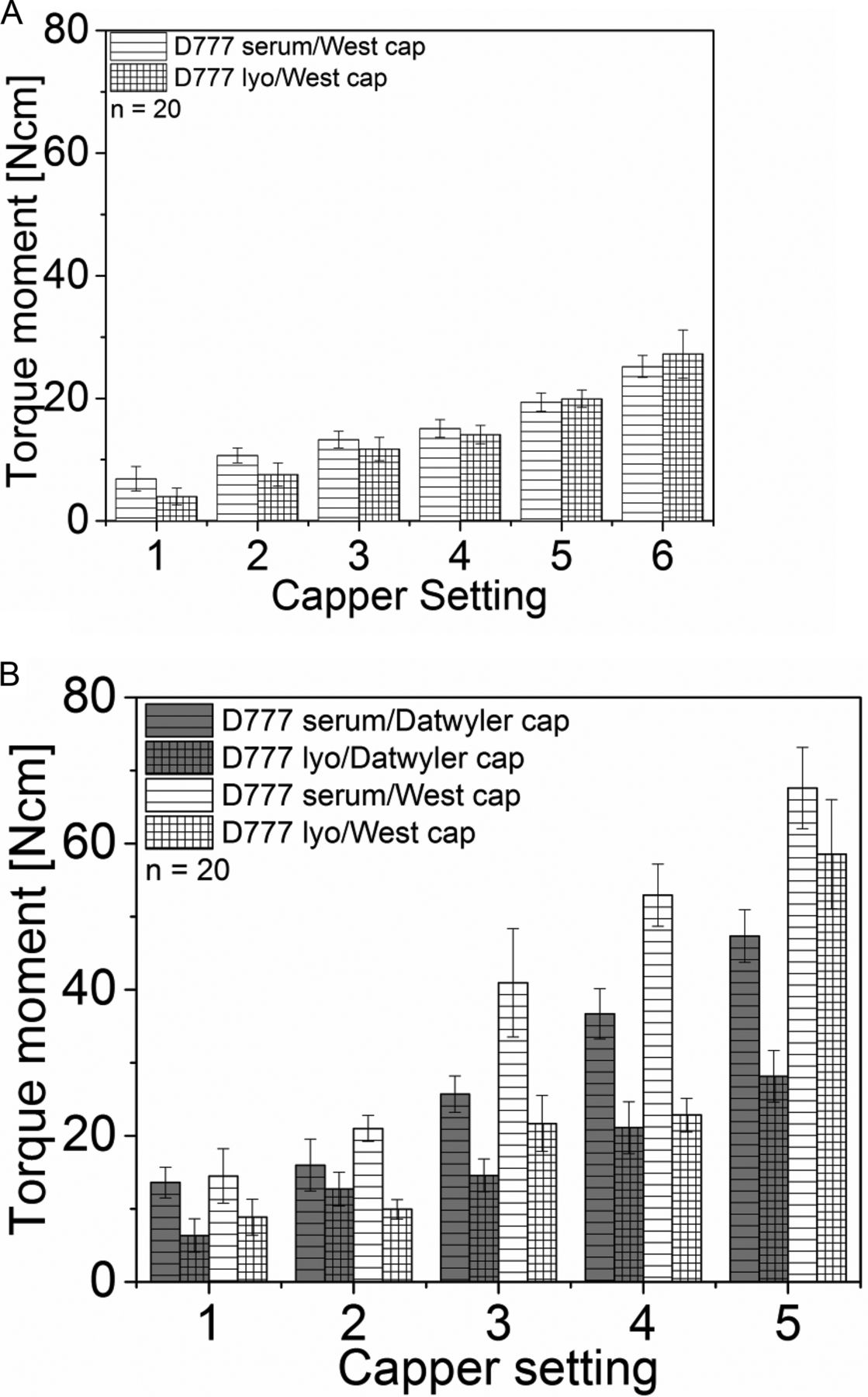
Torque moment measurements of (A) 3 mL vials, (B) 15 mL vials. Gray striped bars: Daikyo serum rubber stopper with a Datwyler crimp cap. Gray gridded bars: Daikyo lyo rubber stopper with a Datwyler crimp cap. White striped bars: Daikyo serum rubber stopper with a West crimp cap. White gridded bars: Daikyo lyo rubber stopper with a West crimp cap.
The torque moment required to turn the crimp cap was correlated with the RSF values of the sealed vials (Figure 7). For example, at capping equipment setting 3 the torque moment for 15 mL vials with a serum rubber stopper and a West crimp cap (Figure 6B, white striped) was 40.9 ± 7.4 Ncm, whereas at capping equipment setting 5 the torque moment for the same CCS was 67.6 ± 5.6 Ncm (Figure 6B, white striped). Comparable results were observed for the 3 mL vials (Figure 6A). CCS configuration with increasing RSF values featured increasing corresponding torque moments.
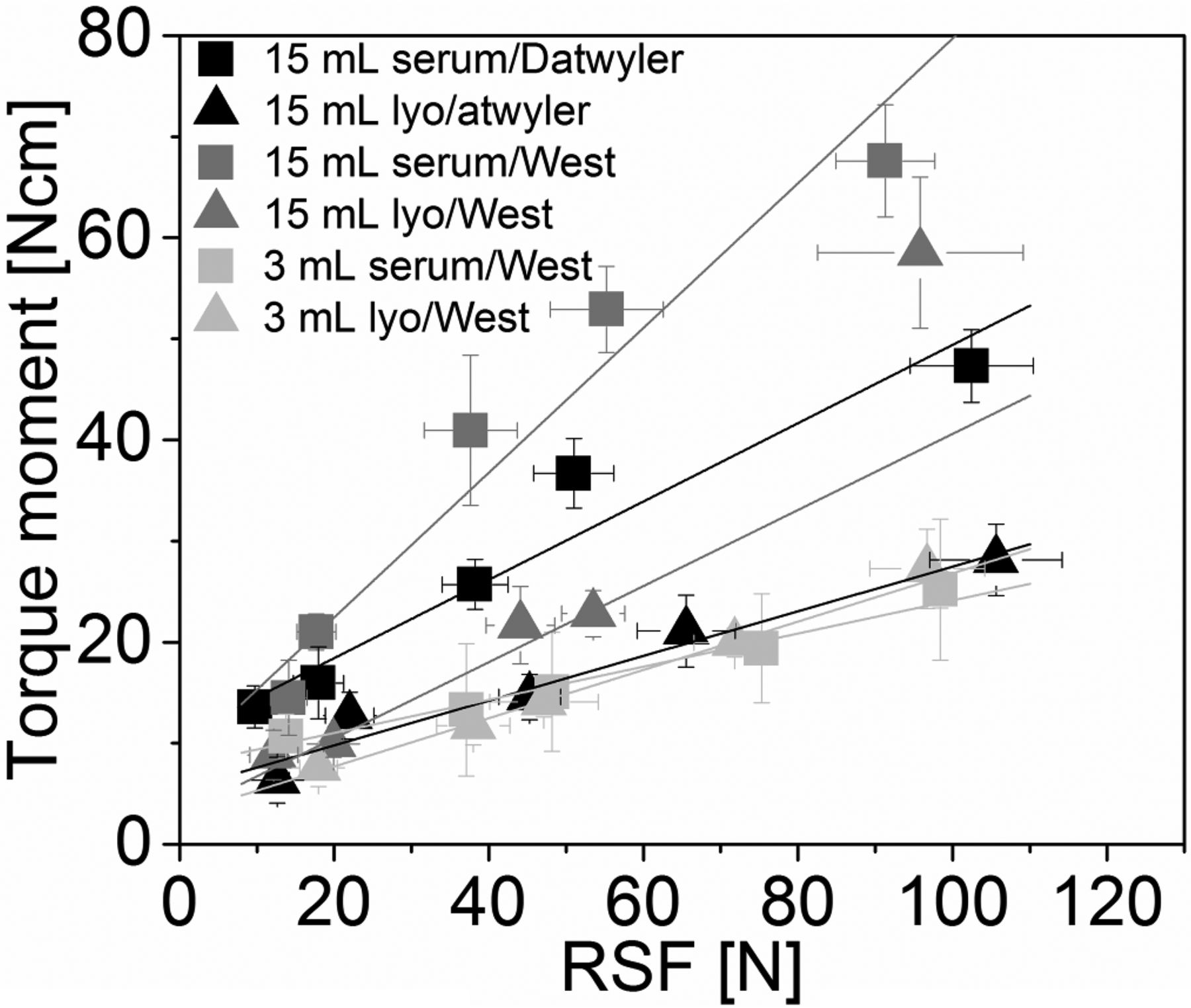
Linear correlation between the RSF and the torque moment (Pearson's r was between 0.97 and 1.00) (Capping equipment setting 5, D777 lyo / West cap was not used to calculate the correlation). Black squares: 15 mL D777 serum rubber stopper, Datwyler crimp cap. Black triangle: 15 mL D777 lyo rubber stopper, Datwyler crimp cap. Dark Gray squares: 15 mL D777 serum rubber stopper, West crimp cap. Dark Gray triangles: 15 mL D777 lyo rubber stopper, West crimp cap. Light gray squares: 3 mL D777 serum rubber stopper, West crimp cap. Light gray triangles: 3 mL D777 lyo rubber stopper, West crimp cap.
A controlled capping process with a defined RSF range defines the torque moment required to turn the crimp cap of a sealed vial. However, the final adequate torque moment cannot be generalized and needs to be defined for a specific CCS configuration on an individual basis.
The Influence of the Rubber Stopper Design (Serum vs Lyo) on the Torque Moment:
The rubber stopper design had only a minor influence on the torque moment for the 3 mL vials (Figure 6A, striped vs gridded bars). For example, at capping equipment setting 3 the torque moment for the serum rubber stoppers was 13.3 ± 1.4 Ncm and for the corresponding lyo rubber stoppers 11.7 ± 1.9 Ncm (Figure 6A). RSF values for serum and lyo rubber stoppers were similar.
In contrast, the rubber stopper design had a major influence on the torque moment for the 15 mL vials (Figure 6B, striped vs gridded bars). The serum rubber stoppers showed higher torque moments in combination with the Datwyler and West crimp caps compared to the corresponding CCSs with a lyo rubber stopper (Figure 6B, striped vs gridded bars). For example, at capping equipment setting 3 the 15 mL vials with a serum rubber stopper and a Datwyler crimp cap had a torque moment of 25.7 ± 2.5 Ncm, whereas the corresponding lyo rubber stopper only had a torque moment of 14.6 ± 2.2 Ncm (Figure 6B, gray striped vs gridded bars). The RSF was on comparable levels for serum and lyo rubber stoppers and consequently did not contribute to the difference in torque moment (Table II). One exception was the CCS with the 15 mL vials with the lyo rubber stopper and a West crimp cap at capping equipment setting 5 (Figure 6B, white gridded bar). At capping equipment setting 5 the CCS with the lyo rubber stopper was on similar torque moment levels as the serum rubber stopper (Figure 6B, white striped vs gridded bar). The lyo rubber stopper bulks up upon excessive capping forces and increases the friction between the West crimp cap and the rubber stopper, although effects are difficult to delineate.
The lyo rubber stoppers used in this study feature a top surface coating to prevent sticking on the lyophilization shelf during the vial closing process at the end of the lyophilization cycle. This top surface coating lowers the friction between the rubber stopper and the crimp cap and consequently lowers the torque moment required to turn the crimp cap on a sealed vial.
The Influence of the Crimp Cap Design (Plastic Finger Connectors vs Pre-cut Metal Bridges) on the Torque Moment:
The torque moment for the 15 mL vials sealed with a Datwyler crimp cap ranged from 6.3 ± 2.3 Ncm to 47.3 ± 3.6 Ncm (Figure 6B, gray bar). At similar RSF values the 15 mL vials sealed with a West crimp cap showed generally higher torque moment values (Figure 6B, gray vs white bars). The torque moment for the 15 mL vials sealed with a West crimp cap ranged from 8.8 ± 2.5 Ncm to 67.6 ± 5.6 Ncm (Figure 6B, white bar).
The Influence of the Rubber Stopper Size (13 mm vs 20 mm) on the Torque Moment:
The rubber stopper size had a major influence on the torque moment required to turn the crimp cap of a sealed CCS. The torque moment for the 15 mL vials ranged from 6.3 ± 2.3 Ncm to 67.6 ± 5.6 Ncm (Figure 6B). At similar RSF values the 3 mL vials showed consistent lower torque moment values than the 15 mL vials (Figure 6A vs 6B). The torque moment for the 3 mL vials ranged only from 4.01 ± 1.36 Ncm to 27.26 ± 3.91 Ncm (Figure 6A). For example, at capping equipment setting 4 the torque moment for the 15 mL vials sealed with a D777 serum rubber stopper and a West crimp cap was 52.92 ± 4.26 Ncm (Figure 6B, white striped bar), whereas the torque moment for the corresponding 3 mL CCS was only 15.08 ± 1.45 Ncm (Figure 6A, white striped bar).
The higher torque moment required to turn the crimp cap of the 15 mL vial featuring the larger vial head can be explained by the larger contact surface area at the rubber stopper—glass vial and rubber stopper—crimp cap interface. The larger contact surface area creates a larger friction when the crimp cap is turned, resulting in higher measured torque moments.
In conclusion, the CCS configuration and the RSF influence the torque moment required to turn the crimp cap of a sealed vial. A linear correlation between RSF and torque moment was observed (increased RSF values had increased corresponding torque moments). The CCS with serum rubber stoppers showed higher torque moments than with lyo rubber stoppers. The CCS with West crimp caps showed higher torque moments than with Datwyler crimp caps. Finally, the CCS with larger rubber stoppers (20 mm) showed higher torque moments than with smaller rubber stoppers (13 mm).
The torque moment required to turn the crimp cap can be controlled by a defined target RSF range of the capping process.
Flip-Off Removal Force:
The measuring device built in-house (Figure 5) was used to obtain force distance plots of the removal of a flip-off button. The maximum force of the of force distance plot was set as the force required to remove the flip-off button. The West crimp cap features a flip-off button, which is connected to the metal part by pre-cut bridges (Figure 1E,H; Figure 10). The measured force immediately dropped down after the first connector of the pre-cut bridges broke (Figure 8, black and gray bars). In contrast, the flip-off button of the Datwyler crimp cap is connected to the metal part by flexible and elastic plastic fingers (Figure 1B). Therefore, the flip-off button slowly slides off the metal part of the crimp cap and the force slowly drops down (Figure 8, light gray bar).

Force distance plot of the flip-off button removal measurement: Black: 3 mL vial with serum rubber stopper and a West crimp cap. Dark gray: 15 mL vial with serum rubber stopper and a West crimp cap. Light gray: 15 mL vial with serum rubber stopper and a Datwyler crimp cap.
The CCS configuration as well as the RSF suggested only a minor influence on the force required to remove the flip-off button of a sealed vial.
For the 3 mL vials at capping equipment settings 2 to 5, the force required to remove the flip-off button ranged between 18.1 ± 2.5 N and 22.1 ± 4.8 N and was not influenced by the RSF or the CCS configuration (Figure 9A, striped vs gridded bar). Those CCSs featured a measurable force to remove the flip-off button. At capping equipment setting 1 no force could be measured: During the measurement the complete crimp cap was removed because not enough metal was folded under the vial flange to hold the crimp on the glass vial (partially crimped vials/low rubber stopper compression with insufficient cap skirt folded under the vial flange).The RSF for the CCS at capping equipment setting 1 was not measurable (probably below the detection limit), confirming an inadequate capping process. An unintentional complete removal of the crimp cap (with a possible unintentional rubber stopper removal) before patient treatment is not acceptable.
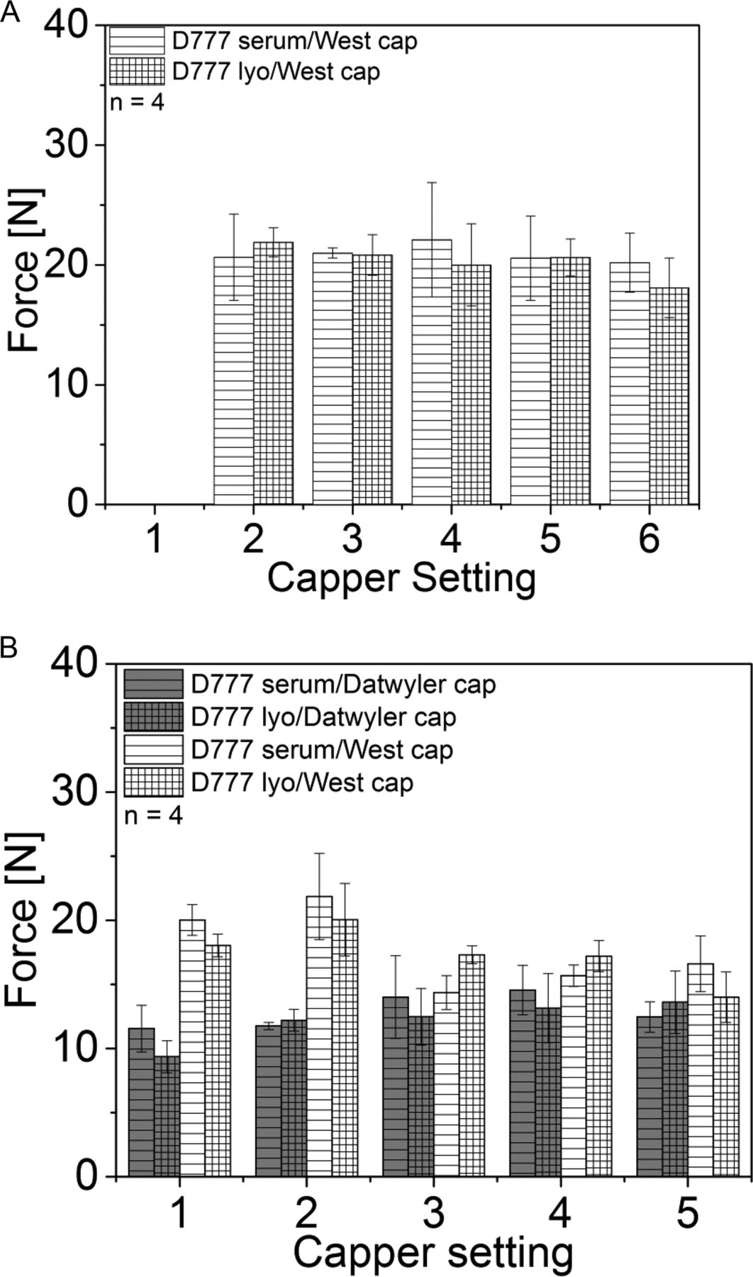
Force required to remove the flip-off button of a sealed CCS: (A) 3 mL vials, (B) 15 mL vials. Striped bars = serum rubber stoppers, Gridded bars = lyo rubber stoppers, Gray bars = Datwylercrim caps, White bars = West crimp caps.
The force required to remove the flip-off button for the 15 mL vials ranged between 9.4 ± 1.3 N and 14.6 ± 1.9 N for the Datwyler crimp caps, and 14.0 ± 2.0 N and 21.85 ± 3.4 N for the West crimp caps (Figure 9B). At capping equipment settings 1 and 2 a difference between the Datwyler crimp caps and the West crimp cap could be observed. The CCS with the Datwyler crimp caps ranged between 9.35 ± 1.26 N and 12.2 ± 0.86 N, whereas the CCS with the West crimp cap ranged between 18.025 ± 0.9 N and 21.85 ± 3.4 N. At capping equipment settings 3 to 5 no major difference between the different CCS and capping equipment settings could be observed (Figure 9B). However, all CCSs featured measurable forces to remove the flip-off button; no partially crimped vials were observed.
For the 15 mL vials at capping equipment setting 1 and 2, the West crimp caps featured similar force values as the 3 mL vials. Upon higher capping forces the pre-cut metal bridges (Figure 1E,H, Figure 10) might weaken and decrease the force required to remove the flip-off button. However, no physical damage to the pre-cut bridges could be observed by CT images (Figure 10), and the functional integrity of the flip-off button (with measurable flip-off button removal forces) was retained over the complete RSF range investigated.
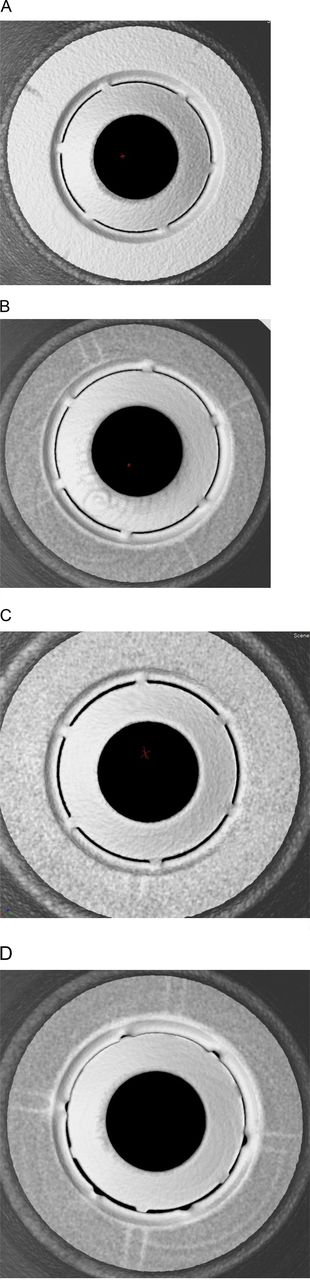
CT images of crimp caps: (A) Uncrimped 15 mL vial with a serum rubber stopper and West crimp cap (bottom-up view), (B) 15 mL vial with a serum rubber stopper and West crimp cap sealed with capping equipment setting 3 (bottom-up view), (C) 15 mL vial with a serum rubber stopper and West crimp cap sealed with capping equipment setting 5 (bottom-up view), (D) 15 mL vial with a serum rubber stopper and West crimp cap sealed with capping equipment setting 5 and intentionally broken pre-cut metal bridges after the capping process (bottom-up view).
In conclusion, the CCS and the capping process only had a minor influence on the force required to remove the flip-off button. All vials featured measurable flip-off button removal forces except for the inadequate/partially crimped vials. Partially crimped vials lead to a complete removal of the crimp cap when the flip-off button was removed, which is not acceptable; however, this was easily detectable by flip-off removal force measurements.
CT Measurements:
The Datwyler crimp caps and the West crimp caps (13 mm) showed measurable and consistent force values required to remove the flip-off button for all capping equipment settings and were not investigated further.
The CCSs containing the West crimp caps (20 mm) were further analyzed by CT to investigate the pre-cut bridges between the flip-off button and the metal part. CT images were acquired of the complete CCS consisting of a vial, rubber stopper, and a crimp cap with a plastic flip-off button. However, the rubber stopper and the plastic flip-off button were filtered out during the digital image reconstruction process to investigate the metal bridges.
No difference between uncrimped crimp caps placed on a vial and a rubber stopper (Figure 10A) and crimp caps, which were processed with capping equipment settings 3 and 5 for the 15 mL vials (Figure 10B,C) could be observed. As a control, intentionally broken pre-cut bridges were investigated and could clearly be observed by CT measurements (Figure 10D). The CT images, which can reveal possible crimp cap defects, confirmed the measurable force required to remove the flip-off button; however, they cannot explain the force drop between capping equipment settings 2 and 3 for the CCS with a West crimp cap (20 mm) (Figure 9B).
Studies with Commercial Manufacturing-Scale Capping Equipment
In addition to the experiments with the laboratory-scale capping equipment, the Bausch&Stroebel RVB4090 commercial-scale manufacturing capping equipment was used to produce CCSs with different RSF values to investigate the torque moment required to turn the crimp cap and the force required to remove the flip-off button of a sealed CCS.
The difference in the distance of the capping plate-to-plunger led to RSF values of 31.6 ± 4.2 N (corresponding to Figure 11, black bar), 46.65 ± 5.0 N (corresponding to Figure 11, gray bar), and 72.9 ± 6.80 N (corresponding to Figure 11, white bar). The vials showed comparable trends and absolute values for the torque moment measurements compared to the vials sealed with the laboratory-scale capping equipment (commercial- and laboratory-scale vials both featured a 20 mm vial head; the difference in vial size is considered to be negligible for the measured torque moment). For example, the vials manufactured with commercial-scale capping equipment had a RSF of 46.65 ± 5.0 N and a corresponding torque moment of 29.47 ± 3.8 Ncm. The theoretical torque moment calculated from the linear fit (from Figure 7, black line squares) would be 28.7 Ncm.

(A) Torque moment measurements of CCS manufactured using commercial-scale capping equipment, (B) Flip-off button removal force measurements of CCS manufactured using commercial-scale capping equipment.
In addition, the force required to remove the flip-off button of commercially manufactured CCSs was investigated. The RSF had no influence on the force. All CCSs had force values between 16.3 ± 1.6 N and 17.3 ± 1.0 N and was on a comparable level as the laboratory-scale vials 9.4 ± 1.3 N to 14.6 ± 1.9 N.
In conclusion, the measurements of the vials manufactured with commercial-scale capping equipment correlated well to the measurements performed at laboratory scale. The torque moment required to turn the crimp cap of a sealed vial fitted the linear correlation established at laboratory scale. The capping process had no significant influence on the force required to remove the flip-off button in the RSF range investigated.
Conclusion
Different CCSs were sealed with several capping equipment settings to obtain vials in a wide RSF range. The torque moment required to turn the crimp cap of a sealed vial correlated to the measured RSF. CCSs with large vial heads, serum rubber stoppers, and West crimp caps had higher torque moments than CCSs with small vial heads, lyo rubber stoppers, and Datwyler crimp caps.
The force required to remove the flip-off button was not influenced by the capping process in the studied process ranges. All vials featured measurable force values required to remove the flip-off button, except the partially crimped vials with RSF values below the detection limit of the RSF tester. The definition of a target RSF range may support an adequate capping process and minimize inadequately crimped vials, where the flip-off button cannot be removed without removing the complete crimp cap.
Conflict of Interest Declaration
The authors declare that they have no competing interests.
- © PDA, Inc. 2016


Jump to section
Related Articles
Cited By...
- Container Closure Integrity of Vial Primary Packaging Systems under Frozen Storage Conditions: A Case Study
- Use of a Predictive Regression Model for Estimating Hold-Up Volume for Biologic Drug Product Presentations
- Quantifying the Vial-Capping Process: Reexamination Using Micro-Computed Tomography
- Balancing Container Closure Integrity and Aesthetics for a Robust Aseptic or Sterile Vial Packaging System
- Residual Seal Force Testing: A Suitable Method for Seal Quality Determination of (High Potent) Parenterals