
Abstract
Container closure integrity (CCI) is one of the requirements for a sterile packaging system. For vial-based systems, the capping process is a critical step in creating and ensuring an adequate seal with acceptable CCI. Container closure integrity tests (CCITs) such as the dye ingress and the helium leak rate are two methods among many that, in the appropriate scenario, help to challenge this required attribute. The use of locked-in stopper compression (compression under the crimp seal post capping) enables correlation of these methods to CCI and seal quality. In fact, the overall acceptability of a seal can be evaluated using quantitative and qualitative methods. Usually lost in these assessments is the existence of seal cosmetics as an essential additional seal quality attribute. Unacceptable cosmetic quality can have a major impact on manufacturing (reduced batch output, high yield cost, etc.) and user (perceived low quality, brand image, potential injury, etc.) experiences. Interestingly, the aesthetics of a seal is also impacted by the capping process which is quite complicated because the acceptance criteria for aesthetics of a seal is subjective. Ultimately, this affects commercial manufacturing efficiency and CCI. Here, we present a simple methodology for package selection and evaluated multiple package configurations using locked-in stopper compression (through residual seal force, RSF) measurements and seal aesthetics analyses (using a semi-quantitative aesthetics scale). The integrity of the seals was analyzed using multiple CCIT methods. We determined that component dimensions such as the seal length play a major role in obtaining proper seal aesthetics and integrity. This can ultimately enable the selection of robust packaging components that provide an adequate range of manufacturing conditions without cosmetic defects. A failure to do this could result in high rejects during drug product visual inspection culminating in low batch yield, high costs or could pose harm to patients if suitable CCI is not achieved.
LAY ABSTRACT: One common container closure system for parenteral drug products includes a glass vial, rubber stopper, and aluminum crimp seal. The capping process, in which the elastomeric closure is compressed against the vial by means of an aluminum crimp seal, is key to ensuring an optimal seal from both an aesthetic and CCI perspective. Ensuring a robust capping process must include a deep and necessary understanding of the interconnection between the selected components, desired aesthetics of the seal, stopper compression, residual seal force, and CCI; the way in which the capper is configured (sealing parameters) will play a part in addition to the “style” used in manufacturing. Previous published studies have focused on capping process controls to only ensure CCI. Here, we present a useful methodology for selecting appropriate components and capping process parameters using a scaled-down approach to achieve elegant seal quality and CCI simultaneously. Dimensional analysis and capping design of experiments (DOEs) were conducted on lab-scale equipment that was representative of commercial configurations. The seals made from these studies were analyzed using residual seal force, helium leak, and dye ingress methods. The results and their implications were discussed with regard to the operating principle of the rail-type capping machine.
1. Introduction
The U.S. Food and Drug Administration defines container closure systems as “the sum of packaging components that together contain and protect the dosage form” (1). Such a system should be integral and designed to prevent product loss and maintain sterility throughout its life cycle, thus ensuring product quality and patient safety. Consequently, when analyzing the container closure integrity (CCI) of a typical parenteral primary packaging system containing a glass vial, a rubber stopper, and an aluminum crimp seal, it is important to evaluate the components for an integrated fit. The component stack-up and tolerance ranges, for example, provide preliminary guidance on components compatibility when combined. The primary alignment of the individual components forms a critical initial seal (2, 3), which then enables an acceptable seal after crimping.
Variations in component dimensions can exacerbate the challenges associated with creating an acceptable seal. Indeed, efforts can be taken to reduce the impact through a combination of process improvements or by selecting components with tighter tolerances. Regardless, the assessment and optimization of capper settings used in the manufacturing process could help mitigate the effects of component dimension and physical property variations. Appropriate capping enables the maintenance of an adequate post-capping or locked-in compressive force that will be robust; creating a vital protection in the presence of minor defects that could otherwise compromise the sealing surfaces (2, 3).
The vial capping process necessary to produce the adequate locked-in compression is a complex interplay of several process parameters and the component configuration (4⇓⇓–7). For example, previous works have shown that measured process parameters such as capping precompression force or capping plate height are not adequate predictors of the final capping result (4). For sealing rubber components, the elastic property is important. An applied stress (sealing force) induces a corresponding strain that creates a contact stress. This stored internal energy is the residual seal force (RSF).
Therefore, the RSF is the stress a compressed elastomeric closure flange continues to exert on a vial land sealing surface after the application of an aluminum seal (crimping), and it provides an indirect estimate of the elastomeric closure compression (7⇓⇓–10).
Sufficient compression is essential to seal integrity. Additionally, because of the viscoelastic properties of the stopper, RSF is time- and temperature-dependent. The nature of these dependencies and their impact on CCI have also been reported (6, 11⇓–13).
Furthermore, an RSF tester can be used to measure RSF (5); it is a useful tool that is independent of the capping equipment and enables comparison. Briefly, upon capping, the closure flange is compressed against the vial land sealing surface. The closure acts like a “compressed spring”. The tester exerts force on the cap or stopper. When the tester force exceeds the closure compression force, graphically, the stress-strain slope (rate of change) drops. The “knee” or the edge of the drop in the curve equals the RSF.
The previous studies indicated that the RSF is a parameter that can assist in ensuring the consistency of the crimp capping process and that an RSF range can be obtained for a component combination set but needs to be reestablished for different capping equipment (9). Although there may have been conflicting reports on the correlation of the RSF with the CCI (10, 13, 14), a recent study presented a more robust correlation as well as statistical modeling, resulting in reduced acceptable lower RSF limits (2). Furthermore, both qualitative and quantitative approaches in applying the RSF to container closures have been provided (2, 11, 15). Lam and Stern (15) presented qualitative visualization methods to assess the fit between a stopper and a vial, whereas Mathaes et al. (11) described the correlation between RSF, torque moment (turning of the aluminum crimp cap), and button flip-off removal force. Ovadia et al. (2) developed a quantitative, nonsubjective method for the capping process in a manufacturing environment to ensure CCI; this method showed low variability in RSF measurements.
Although the RSF can be a useful tool in packaging and capper settings development, the partially artisanal nature of a capping machine can lead to somewhat subjective cosmetic defects for a seal with acceptable or high RSF values. This may prompt technicians to “dial back” on capping forces, lowering the RSF values in the process and potentially sacrificing acceptable CCI to improve aesthetics. Indeed, the existence of seal cosmetics as an essential additional seal quality attribute is usually lost in preliminary container closure systems assessments. Therefore, we propose a balanced approach to assess the robustness of the container closure system capping process with respect to the CCI and the aesthetics using model packaging components and also provide a general illustrative guide to selecting packaging components to satisfy CCI and aesthetics. Data were obtained from capping analysis, compression settings, RSF, and CCI test (CCIT) measurements. The implications of the results for the development of adequate and robust container closure systems are discussed.
2. Materials and Methods
The general steps used in assessing the packaging components' compatibility are described in Figure 1.

Criteria for primary container (vial) packaging system selection during development.
2.1. Materials
The components used in this study are shown in Table I and Figure 2A, B. These components are standard parts within the pharmaceutical industry and are widely used in many drug product configurations.

(A) Stopper A with vial and crimp seals and (B) Stopper B with vial and crimp seals.
Packaging Components Used in the Study
2.2. Methods
2.2.1. Dimensional Analysis:
The compatibility of the dimensions of the components was evaluated via an interference fit and tolerance stack up that has been previously documented (16). Briefly, a range of interference limits is obtained by finding the differences between the stopper plug diameter (PD) and the vial finish internal diameter (ID). The minimum interference was calculated using the minimum stopper PD and the maximum vial opening ID. Similarly, the maximum interference was calculated using the maximum stopper PD and the minimum vial opening ID.
Thus, the interference fit evaluates the dimensional overlap of stopper PD with the finish ID of the glass vial. Excessive interference could lead to stopper pop up during product manufacture, whereas an insufficient interference may exacerbate leakage. Although this can also be measured, a theoretical exercise was performed here.
Secondly, we calculated the excess skirt length (or overhang) of an aluminum skirt as depicted in Figure 3. The primary seal for a vial is the locked-in compression by the crimp achieved through the vertical deformation (applied force) on the stopper. As a result, an appropriate stack-up assessment that will incorporate the stopper compression and evaluate the suitable aluminum seal skirt length needed for an acceptable crimp to a vial was performed.

(A) Tolerance stack-up diagram and (B) Sample X-ray images of various overhangs.
2.2.2. Components Processing:
To maintain the integrity of a parenteral vial closure system, several capping machine factors such as the capping force, location of the crimping relative to the pressure block, shim sizes, and so forth can be critical to the overall capping process. For example, an insufficient capping force can result in leakage at the interface of a vial closure seal, whereas excessive capping force risks package damage with the potential for glass breakage—situations that can be worsened with extreme component flange stack heights (1).
It is not uncommon for technicians to increase the capping force in the hope of increasing the vertical compression of the stopper and potentially maintaining adequate container closure. However, studies indicate that this may not always be true. Recently, Mathaes et al. (6) reported that the initial force exerted by the capping machine does not provide enough information on the capping process and the resulting post-capping stopper compression and RSF, demonstrating that the vial capping process is a complex interplay of several process parameters of which the initial capping force is one.
In contrast to the capping force, the RSF does present indirect measurements regarding seal tightness and seal integrity. These two dynamics, compression and RSF values, are proportionally influenced. The more compression a stopper endures the greater the force exerted on the vial by the flange, which in turn results in a higher RSF value (6).
2.2.2.1. Capping Process:
Three aluminum crimp seals of different lengths (and cap colors for clarity) and two types of stopper formulations were used to assemble six different package configurations using various capping settings. The same type of vial (ISO 25 R) was used for all packages. The different packaging samples were manufactured on a lab-scale capping machine to obtain multiple ranges of stopper compression and RSF.
The samples were sealed using a small-scale RW-4 capper from Genesis Packaging Technologies. The RW-4 capper simulates the sealing capabilities of the Genesis RW-600 model used in typical commercial production. Sealing components of the RW-4 include the RW.Z.13,868 sealing rail, pressure blocks, and shim, which are all interchangeable with the RW-600. Additionally, the RW-4 has four sealing spindles versus the 12 sealing spindles the RW-600 contains. Overall, the machine replicates the functionality, and the capper parameters that need to be considered are the head height, pressure block, vial rest position, precompression force, and sealing rail positions. The capping parameters used are presented in Table II.
Capping Parameters Used in the Study
In this study, the RSF was measured using a Genesis RSF tester (Model # AWG, Serial # 173) in which a slow, constant rate of strain is applied to the top of a capped vial and the resistance to package compression is monitored thereby generating a stress-strain profile. The RSF measurements were taken immediately after capping and after 24 h.
2.2.2.2. Container Closure Integrity:
Subsequently, groups of samples were analyzed for CCI using helium leak (25 samples per condition) and dye ingress methods (100 samples per condition). These methods were employed to evaluate whether certain component combinations provide adequate CCI across a range of compression and RSF conditions.
2.2.2.3. Aesthetics Analysis:
Although the aesthetics ratings can be subjective, Table III provides some guidance on a number scale. This scale was developed for this study for experimental purposes only and to enable adequate semiquantitative analysis. It should not be considered as an industry standard. In fact, aesthetic acceptability ratings will vary from site to site and from company to company. Here, crimps with >50% overlap under the vial neck with minor defects and those that have full overlap around the circumference with no defects are deemed acceptable. These are given ratings of 4 and 5.
Aesthetics Scale Used
3. Discussion of Results
3.1. Dimensional Analysis
The calculated theoretical interferences for the components used in the study are presented in Table IV. It is important to maintain integrity before crimping. Previous work suggested about 3%–5% interference as an appropriate range to mitigate stopper pop out before crimping and potential package leak post capping (16). The results showed about 5% theoretical interference fit for both components combinations used in the study.
Interference Fits for Stoppers Used in the Study
With respect to the tolerance stack up, in general, the aluminum skirt overhang that exists should be less than the lip width of the vial. An insufficient overhang could lead to inadequate crimp material leading to potential loss of product sterility. An excessive overhang could lead to aesthetically displeasing crimps, which could have severe implications during the capping process and lead to inspection rejects with lower batch yield. This is further illustrated in Figure 3A, B.
Work by Morton (7) has shown that when a rubber stopper's flange is compressed to an optimal percentage, measurable leak rate cutoff can be achieved. Theoretically, at ∼20% for 20 mm stopper configurations, the measurable leak rate cutoff will be achieved even when certain sealing surface imperfections are present. It should be noted that the physical properties of the rubber, including the thickness and diameter of its flange, may influence the amount of compression needed. Furthermore, there is a correlation between leak rates and the percentage a rubber stopper's thickness is compressed.
Using a 20% compression for the stopper and nominal dimensions, the overhangs for the ISO 25 R vial for all three crimp seals are shown in Table V. These values are all less than the minimum lip width for the vial (1.125 mm). Although not absolute, this is a good indication of some level of compatibility between the components. The theoretical calculations here helped inform the actual capping studies that were performed, with compression ranges of between 5% and 32% obtained.
Overhang for Various Seal Skirt Lengths at Nominal Dimensions
It should be noted that these calculations are shown for nominal dimensions. A more rigorous stack up should be performed to understand the potential ranges for each skirt length. The 6.9 mm skirt length, for example, would have longer overhangs at the lower limits of the vial flange dimensions or at higher stopper compression.
Furthermore, because the design of the ISO 25 R vial flange is comparable to that of other ISO vials, this analysis may be similar for other ISO vials (from 6 R to 30 R). However, it is important to carry out a quick confirmatory study (or studies) with each container closure system to support use with a drug product as there exist numerous nuances between similarly sized ISO vials from different vendors.
Finally, these dimensional assessments are only the first steps that are usually taken to determine the compatibility of packaging components that can maintain an appropriate seal integrity when used together.
3.2. Components' Processing
3.2.1. RSF and Compression:
The relationship between the stopper compression and the RSF is shown in Figure 4A, B. First, the results showed that stopper compression and RSF were proportionally correlated. This corroborates earlier studies by Davidson and Mangus (16). Also, both stoppers achieved a maximum compression level of ∼30% with similar RSF values for multiple seal skirt lengths. This clearly indicates that compression levels (or RSF) can be a quantity for comparison of components compatibility independent of the capping process. Furthermore, the figures showed that a 20% stopper compression does in fact reduce the likelihood of CCI failure given the corresponding high RSF values.

(A) Correlation of stopper compression and RSF for stopper A and (B) Correlation of stopper compression and RSF for stopper B.
The RSF value will continue to gradually decrease over time because of the rubber stopper's stress relaxation. However, it is assumed that the value will not drastically decrease from the value obtained after 24 h based on unpublished internal data (17). As a result, the RSF measurements were taken immediately after capping and after 24 h (Table VI). The RSF values shown in Table VI were obtained under different capping conditions that allowed various ranges of RSF to be obtained for each stopper/seal combination. The RSF values obtained ranged from about 5 lbs. to 15 lbs. with reductions of between 3% and 12%.
Average RSF Measurements
3.2.2. Container Closure Integrity:
The results of the helium leak rates are presented in Figure 5. As shown, all but three samples had results that indicated leak rates below 1.6 × 10⁻⁶ standard cc/s; values below this rate are associated with a substantially reduced risk of microbial ingress, as shown by Kirsch et al. (18). Kirsch demonstrated the relationship between leak rate and the probability of microbial ingress (18). The failed samples (two from stopper A and one from stopper B) were made using the shortest skirt length (6.9 mm) and at low capping settings, which resulted in the inability to pull a vacuum during the testing process, representing gross leaks. The RSF values of the failed samples were 2.7 lbs., 7.4 lbs., and 2.6 lbs.

(A) Helium leak rate results with comparable measured RSF values for stopper A and (B) Helium leak rate results with comparable measured RSF values for stopper B.
The dye ingress results are presented in Table VII.
Dye Ingress Test Results for All Combinations Tested
4. Commercial Manufacturing: Balancing CCI vs Aesthetics for Robust Packaging Solutions
The preceding analyses provide a solid technical foundation for the selection of packaging components for vial-based systems. However, there exists an additional seal quality attribute that could play a major role in CCI and ultimately in commercial manufacturing: cosmetics. Although the aesthetics of a seal are subjective (could vary from technician to technician and from site to site), it nonetheless should be an important consideration for components selection. In other words, the robustness of the packaging components must include the ability to provide an adequate range or flexibility of manufacturing conditions without cosmetic defects. A failure to do this could result in high rejects during drug product visual inspection, culminating in low batch yield and high costs. Addressing this, however, is nontrivial as Figure 6 indicates.

Quality attributes of a seal: Competing factors.
High locked-in compression can be an indicator of lower leakage risk. However, if the compression is too high, the overhang of the crimp seal could become too long so that an unacceptable cosmetic quality is obtained (bottom right corner in Figure 6). This may lead technicians (given the semiautomatic nature of the capper) to reduce the compression by dialing back on the capping forces (or other controls). The risk is obtaining an acceptable aesthetic but poor CCI owing to low locked-in compression force (top right corner). Herein lies the problem of the fine balance that must be maintained to avoid the gray colored boxes in Figure 6.
The skirt length of the crimp seal, therefore, does provide one avenue to address or mitigate this issue. Indeed, Figure 7 shows a difference between the cosmetics of the seal obtained from a standard 7.5 mm skirt crimp (white) and a shorter 7.3 mm skirt length (dark blue) when sealed with high enough compression to maintain adequate container closure. This ultimately leads to lower rejections per run for the shorter skirt and hence better efficiency for the manufacturing site. Figure 8 is an example of such data.

Competition between compression (RSF) and skirt length (cosmetics); Unacceptable 7.5 mm skirt crimp and Acceptable 7.3 mm skirt crimp.

Inspection rejects because of cosmetics quality (Note: Regular skirt: 7.5 mm skirt length, Short skirt: 7.3 mm skirt length).
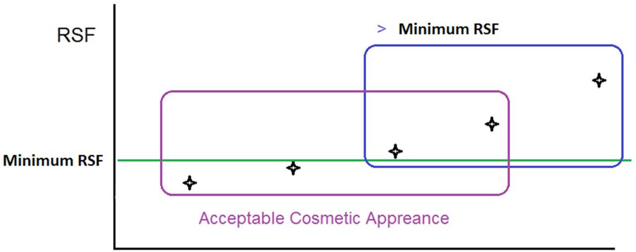
The final analysis of this study was to determine the robustness of the skirt length in balancing the CCI and the resulting cosmetics. The robustness is indicated as the size of the intersection of the boxes in Figure 9.

Determining the robustness of packaging configurations.
As previously mentioned, Table III provides some semiquantitative ratings of the aesthetics acceptability for the purpose of clear illustration in this study. Here, a 4 or 5 rating is deemed acceptable, whereas a rating of 3 or less is not.
The results for all combinations tested are subsequently plotted in accordance with the aesthetics scale shown in Table III.
The plots of Figure 10A, B provide some guidance and insights into which skirt length might be more robust in combination with a specific vial and stopper. For example, the 7.3 mm skirt (blue) showed a tighter range of acceptable aesthetics at high RSF values. This might suggest a potentially better flexibility in manufacturing to satisfy the desired CCI and acceptable appearance quality.

(A) Combining RSF and aesthetics for Stopper A and (B) Combining RSF and aesthetics for Stopper B.
Furthermore, similar to previous work, the study showed that RSF enables an attribute-controlled process (6), including the use of a semiquantitative yet consistent aesthetic scale that can also be transferred. Thus, the overall process control is achieved.
5. Implications
The implications of these results are quite significant. First, the studies support previous reports that low RSF values can indicate a risk of CCI failure. The results also showed that CCI can be maintained using a range of component sizes such as skirt lengths of the aluminum crimp. Indeed, the skirt length was shown to play a potentially major role in maintaining the balance of CCI and desired aesthetic appearance. Moreover, the subjective factor of visual inspection and/or aesthetics can have a significant impact on the manufacturing rejects rate. In order to address this, we proposed a sample aesthetics scale that is semiquantitative and consistent.
Finally, this work depicts a process control strategy that can be incorporated in the design of a packaging component system that is robust enough to meet various manufacturing challenges. Figure 11 provides a summarized outline of the necessary integration that is needed between the components and the process in a manufacturing setting.

Integrating components and process to achieve a robust packaging system.
6. Concluding Remarks
In this study, we present a general framework that can be used to identify and select packaging components that will satisfy CCI and desired aesthetics using six model container closure systems. The results showed that the skirt length of the aluminum crimp could play a potentially major role in maintaining the balance of CCI and desired aesthetic appearance. This work provides a basis for how the use of RSF and a scale for aesthetics along with other aspects like dimensional analysis allows one to select the right components and control the process independent of the process equipment and the site.
Conflict of Interest Declaration
The authors declare that they have no competing interests.
Acknowledgments
The authors would like to thank Ryan Ly, Casey Tyrell-Pawlowic, Dana DeSantis, Christina Evans, and Elizabeth Moroney of Bristol-Myers Squibb's Global Product Development and Supply Group for their support in the creation of samples, CCIT, and aesthetics analyses.
- © PDA, Inc. 2019


