
Abstract
All products labeled as sterile are required to be free of microbial contamination throughout their shelf life (obligatory critical quality attribute). Container closure integrity (CCI) needs to be addressed with a holistic life cycle strategy comprising adequate primary packaging components selection and the assessment of critical unit operations and critical process parameters (CPPs) according to quality by design (QbD) principles. The helium leak method is currently the most sensitive CCI test method and preferably used for the initial container closure system (CCS) qualification and characterization studies. Currently, two different measuring principles are used in the pharmaceutical industry, and no data is available in the public domain for typical method performance parameters such as accuracy, precision, intermediate-precision, and limit of quantification of the method. Furthermore, the performance of different types and sizes of artificial leaks as well as certified helium leak standards have not yet been characterized across different test laboratories. In this multicompany study, we shared 17 artificially prepared leak samples using the most common types of artificial leaks in relevant nominal size ranges that are commercially available or can be easily prepared in a laboratory. Each participating company generated results according to their in-house methods, applying their established test parameters as the aim of the study was not to create a standard for helium leak measurements, but to compare real-world performance between different laboratories. Consequently, this study is not an interlaboratory study using the same test method across laboratories.
- Container closure integrity testing
- Helium leak test
- Artificial leaks
- Industry multicompany study
- Container closure system
- Primary packaging
- USP <1207>
Introduction
All products labeled as sterile are required to be free of microbial contamination throughout their shelf life as an obligatory critical quality attribute. Container closure integrity (CCI) addresses the maintenance of integrity to prevent microbiological ingress in sterile product packaging until the time of use (1). The CCI and sterility regulatory environment is complex, and sometimes country specific requirements need to be applied. However, these regulations typically do not provide clear practical guidance on how to perform CCI tests (CCITs) (1) CCI failure of a sterile drug product can lead to batch rejection to prevent potential subsequent severe safety impacts for patients.
CCI needs to be addressed with a holistic life cycle strategy comprising adequate primary packaging components selection and the assessment of critical unit operations and critical process parameters (CPPs) according to quality by design (QbD) principles. CCI testing of finished drug products (e.g., during stability studies) can be an additional cornerstone in this holistic approach (2).
Several CCIT methodologies have been described and successfully implemented in the pharmaceutical industry. The choice of suitable CCIT method should consider the intended purpose, for example, container closure system (CCS) qualification vs. routine manufacturing, prior knowledge of the CCS, the CCS type, format, and material, the product properties, the desired test duration, the required sensitivity, and considerations of a reasonable sample size. The performance of a selected CCIT method should be characterized, and justifiable acceptance criteria must be established (1).
The helium (He) leak method is currently the most sensitive CCIT method and preferably used for the initial CCS qualification and characterization studies. A correlation to microbial CCI testing (mCCI) was established already in 1997 in several studies (3), which led to the He leak acceptance criteria suggested by USP <1207> (4). The He leak test method was described in literature related to specific scientific questions such as capping process characterization, prefilled syringe characterization, artificial leak method characterization, or oral blister testing.
The He leak method is a destructive test and can hence not be applied for 100% testing. In addition, no off-the-shelf He leak CCIT test equipment with ready-to-use chambers or fixtures to test different containers (e.g., glass vials, syringes) is commercially available so far. Hence, any end user needs to design, manufacture, and qualify sample holders or test chambers individually (5).
Currently, two different measuring principles are used in the pharmaceutical industry. The He leak flange mode method (“outside-in mode”) uses airtight fixtures comprising the CCS and works with continuous He gas flow (5⇓–7). In the second mode, the He leak chamber mode or “inside-out mode”, the empty (or emptied) test article needs to be prefilled with He gas before it is placed in an airtight chamber of suitable size connected to the mass spectrometry instrument (8).
However, it remains poorly understood how the two different measuring principles of the He leak method, the usage of different He leak test instruments, as well as the application of different parameter settings within different laboratories impact He leak results. No data is available in the public domain of typical method performance parameters such as accuracy, precision, intermediate-precision, and limit of quantification of the method.
Moreover, the performance of different types and sizes of artificial leaks as well as certified He leak standards have not been characterized yet across different test laboratories.
Artificial leaks serve as positive controls and enable the assessment of method performance parameters, for example, characterization of precision, intermediate precision, and limit of quantification. Typical methods for the preparation of such artificial leaks include
Laser drilling into the body of the container (e.g., glass vial).
Laser drilling into a metal plate or tubing that is subsequently integrated into a CCS.
Micro wires inserted at the interface between the elastomeric closure and container.
Micropipettes made of glass inserted into the stopper or glued into an artificial hole in the container.
Capillaries made of fused silica, nickel, or glass inserted into the stopper or glued into an artificial hole in the container.
To characterize those different types of artificial leaks, He leak testing is the method of choice due to its sensitivity, wide working range, and the availability of certified He leak standards (5, 8).
For the multicompany study described in this article, we prepared simulated defects in the most commonly found primary container types for injectables (e.g., glass vials and glass syringes) using the most common types of artificial leaks in relevant nominal size ranges that are commercially available or can be easily prepared in a laboratory. Two out of eight participating laboratories prepared a set of containers with artificial leaks covering laser-drilled holes, copper wires, capillaries, and glass micropipettes. These containers with artificial leaks were then shared and tested sequentially in eight laboratories of major European pharmaceutical companies. Five laboratories used the He leak flange mode method, and three laboratories used the He leak chamber mode method. Purposely, no harmonized instructions were given for how to perform the He leak measurements. Each lab generated results according to their in-house methods, applying their individually established test parameters as the aim of the multicompany study was not to create a standard for He leak measurements but to compare real-world performance between different laboratories. The gathered data should therefore provide a current status of the performance characteristics to be expected across multiple laboratories and should allow an assessment of the comparability of test results for He leak test methods applying different test parameters in different labs. The validity of He measurements was ensured within each laboratory by using calibrated instruments, certified He leak standards, and appropriate assay controls according to in-house procedures (details were not shared for confidentiality reasons). However, this study is not an interlaboratory study (e.g., following principles of ASTM E 691-20) using the same consistent test method across laboratories.
Methods and Materials
Certified He Leak Standards
He (gas) leak standards from Pfeiffer Vacuum with a certified flow rate of 2.18E-04 mbar*L/s (Order No PLT10004) and 3.86E-08 mbar*L/s (Order No PLT10008) were shipped and tested by all participating laboratories. In addition, each laboratory could select and measure any internally available certified He leak standards, which ranged from 6.8 E-09 to 2.4 E-04 mbar*L/s.
CCS Components
Pharmaceutical clear type-I glass vials were used in two sizes (2 mL and 8 mL). The vials were closed using 13 mm and 20 mm coated halobutyl rubber stoppers and standard aluminum flip-off crimp caps. The syringes configuration was a 1 mL long glass syringe with staked-in needles and rigid needle shields (RNS) in combination with a halobutyl rubber plunger stopper.
Negative Controls
Negative controls were also shared between laboratories. For vials, either an iron plug with a diameter reflecting the lower specification of the outer 8 mL vial diameter or an intact closed vial without leak was used. For syringes, an empty 1 mL glass syringe was used, for which the tip was closed by fusion.
Preparation of CCS with Different Artificial Leaks
Vials and syringes with different artificial leaks were prepared in two laboratories. Capillaries, stainless-steel tubings, and glass micropipettes were glued into holes drilled in the glass vial bottom to allow easy use by both measuring principles (inside-out mode and outside-in mode). The 2 mL glass vials were manually crimped with aluminum crimp caps and steel orifice disks of a 13 mm diameter with laser-drilled holes in the middle of the disk instead of a rubber closure. Proper sealing of the steel disks was achieved by rubber ring seals at both sides of the disk.
Laser-drilled holes were sourced from Lenox Laser, USA with certified flow effective diameters (FED): 8 mL glass vials with holes at the bottom or at midheight of the vial with a nominal size of 2 µm (FED of 1.6 µm; 0.046 sccm), 5 µm (FED 4.6 µm, 0.372 sccm), and 10 µm (FED 9.4 µm, 1.53 sccm); 1 mL glass syringes with holes at a distance of approximately 40 mm from the finger flange with a nominal size of 5 µm (FED 4.2 µm, 0.307 sccm) and 10 µm (FED 9.5 µm, 1.60 sccm). Stainless-steel tubing (SS-316 1/16’’) with nominal 5 µm laser-drilled holes (4.8 µm FED, 0.411 sccm) were glued into the glass bottom of an 8 mL vial with the hole positioned inside the vial body. In addition, stainless-steel orifice disks with nominal breaches of 0.3 µm (0.26 µm FED, 0.0012 sccm) (lowest technically feasible diameter), 2 µm (1.8 µm FED, 0.0056 sccm), and 5 µm (4.8 µm FED, 0.396 sccm) were sourced from Lenox Laser.
Fused silica capillaries of a nominal internal diameter of 5 or 10 µm were purchased from BGB, Switzerland (Order No TSP-005,375 or TSP-010,375, respectively), glued into a drilled hole in the bottom of 8 mL glass vials (capillary length 9–11 mm), or placed into a custom-made replacement part for the plunger rubber stopper of syringes (capillary length 8–9 mm).
Glass micropipettes were purchased from World Precision Instruments, Germany, in two nominal sizes of 0.2 µm (TIP2TW1) and 10 µm (TIP02TW1F). Glass micropipettes were glued into a hole in the bottom of 8 mL vials with the fragile glass tip in the inside of the vial body. A fundamental difference between glass micropipettes and fused silica capillaries is that the labeled nominal diameter for microcapillaries is only applied at the tip of the tube, whereas for capillaries, the nominal diameter is realized throughout the entire length of the tube.
Copper wire artificial leaks were prepared by manipulating the CCS sealing area using a copper wire of defined diameter (nominal external diameter of 60 µm, Elektrisola, Escholzmatt, Switzerland). In the case of vials, the copper wire was placed between the rubber stopper and the glass vial, whereas for syringes, the copper wire was placed either between the plunger rubber stopper and the glass barrel or between the RNS and the syringe tip cone (needles were cut to bypass the needle/RNS seal).
Units with artificial leaks were prepared and shipped to the different laboratories. A few showed blockage or were damaged during multiple shipments and handling such as vials with 5 µm fused silica capillaries, vials with 5 µm glass capillaries, and syringes with 20 µm wires inserted in the needle shield. Others increased in diameter, for example, 2 µm laser-drilled hole in glass body of syringe. All related results were excluded from the article, although partial results were available and valid.
Methods
He Leak Outside-In or Flange Mode Method
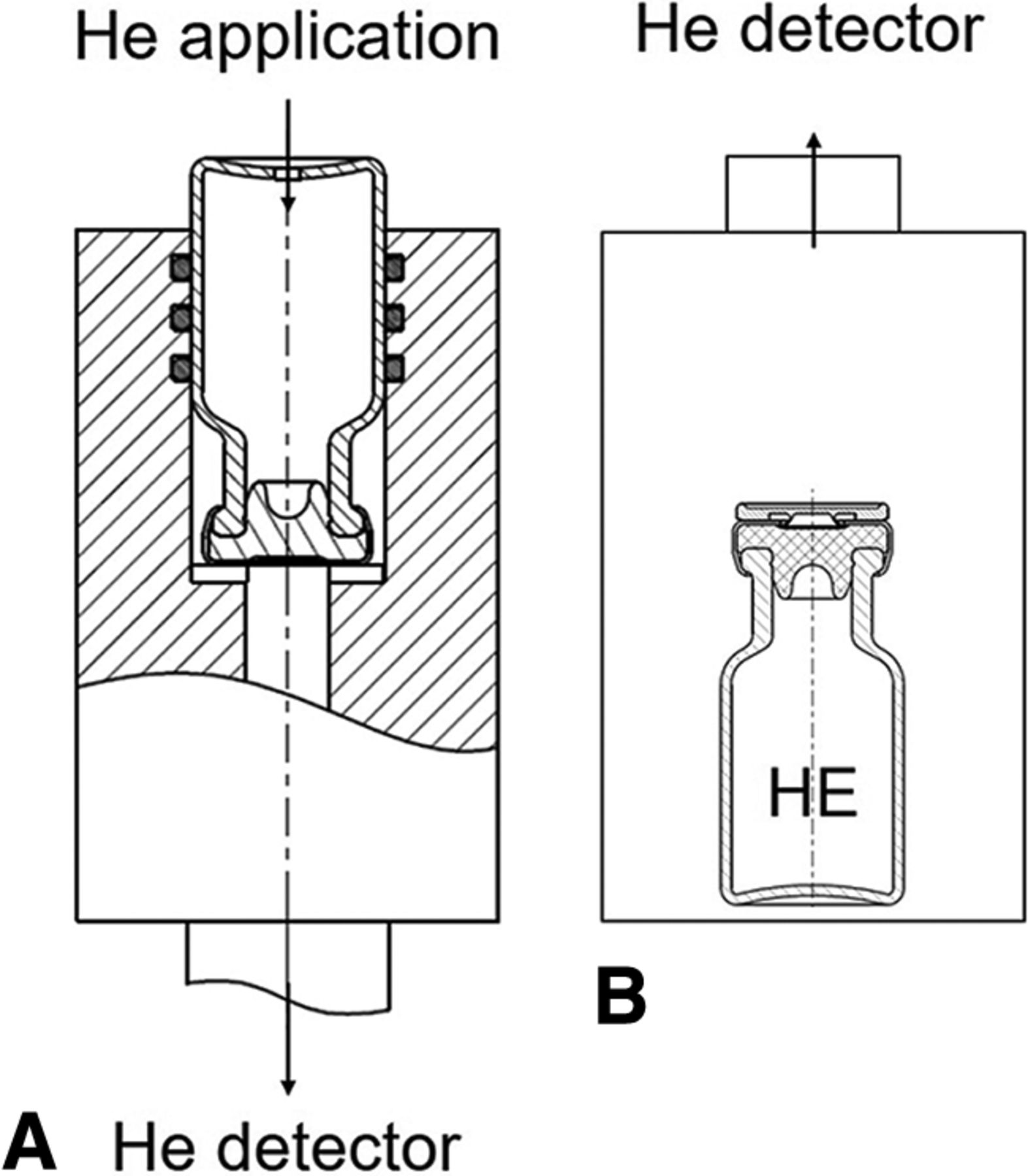
The He leak measurements were performed according to Morrical et al. (5). In brief, custom-made airtight sample holders for syringes or vials were connected to the mass spectrometry detector (Figure 1A). In the case of vials, a small rectangular incision (e.g. approx. 4 mm × 2 mm) was introduced in the glass wall near the bottom of the vial to allow application of He into the vial. Syringes were cut in half, and two separate measurements were performed for the plunger part and the tip cap part. A constant He gas flow was applied during the measurement to ensure He gas saturation.

He leak measurement modes. (A: outside-in mode; B: inside-out mode).
He Leak Inside-Out or Chamber Mode Method
Measurements in the chamber mode were performed on the He-filled containers, which were placed into a gas-tight test chamber connected to the mass spectrometry detector of the He leak test equipment (Figure 1B). The chamber and consequently the test container were exposed to the vacuum generated by the He leak detector. If a leak is present, He will escape from the inside of the container into the chamber and can then be detected by the mass spectrometer.
Study Approach
Test samples were prepared in two laboratories and shipped from laboratory to laboratory for subsequent He leak testing. In addition, no-leaking negative control standards and certified He leak standards at 2 nominal flow rates were shared between laboratories. At the end of the study, the test samples were returned to the laboratory having performed the initial measurements and measured again to confirm adequate performance of the artificial leaks and to assess possible deterioration due to multiple shipments and handling in the course of the study. Of note: These confirmatory determinations at the end were not included in the data analysis. The entire study program in all participating labs was performed within approximately 12 months.
No distinct standardized analytical method procedures for the performance of the He leak testing were shared. Instead, the different laboratories used their individual established standard analytical procedures and equipment (Table I).
Helium Leak Equipment Used at the Different Test Laboratories
The participating laboratories measured the samples in triplicates on Day 1. Then all measurements were repeated on Day 2 in duplicates. All measurements were independent runs; for example, the samples were removed from the chamber or flange of the He leak system after each single measurement and the entire procedure was repeated for the next measurement.
In addition to the measurements on containers shared between all participating labs, a single laboratory measured individually prepared unshared units with artificial leaks to assess assay precision under a best-case short-term measurement condition.
Data was plotted using the Origin lab statistical software, v2019 (Northampton, MA, USA).
The He leak instruments provide a resulting output on a log10 scale always with a defined decimal place (e.g., one or two), which means that the absolute He flow rate results differ in the number of decimal places in the linear scale. For example, a flow rate result of 1.1 E-01 mbar*L/s (0.11 mbar*L/s) features two decimal places, whereas a flow rate result of 1.1 E-03 mbar*L/s (0.0011) features 4 decimal places.
This specialty regarding the He leak instrument’s results output causes several challenges when applying statistical methods such as tests for normality. As a result, no standard deviation, data transformation, or tests evaluating statistical significance were applied. Measured He flow rates were reported in this study as average, minimum, maximum, and span calculated as delta log (log Max-log Min). All results are given in millibar*Liter/sec (Note: He flow rates can be converted to a centimeter cubed/sec by multiplying with a factor of 0.987).
Performance Evaluation of He Leak Measurements
First, typical method performance characteristics such as accuracy, linearity, and precision were assessed within one laboratory on one instrument. Unshared samples were measured to assess the best-case, short-term assay performance and thus provide a baseline for the multilaboratory results. Thereafter, reproducibility, assay accuracy, and performance characteristics of different measurement modes were evaluated across multiple laboratories using different instruments and measurement parameters using the shared standards. Each laboratory verified the accuracy using in-house certified He flow rate standards in parallel to the measurements of the shared samples.
Accuracy of He Leak Measurements
Measurements of certified He leak (flow rate) standards were performed in an equivalent manner across laboratories and between measurement modes, because the standards are directly mounted on the instrument without the use of any chamber or fixture/flange.
Accuracy within Laboratory Using He leak Standards over Extended Time Period:
Certified external He leak standards were assayed over more than 12 months at irregular intervals on one instrument by multiple analysts in one laboratory. Measurements at a certified flow rate of 1.86E-08 ranged from 1.5E-08 to 2.3E-08 with 1.6E-08 on average (n = 51 determinations) representing a relative differenceiii of −15% from the certified value. A second standard at 1.12E-05 was determined on average at 1.1E-05 with a difference of −2%, ranging from 1.0E-05 to 1.4E-05. The span for higher flow rate was slightly lower, that is, 0.15 log units compared with 0.19 log units for the 1.86E-08 certified standard.
Accuracy across Laboratories Using (Un-Shared) He leak Standards over Short Time Period:
Each laboratory measured its own certified He leak standard during the study measurements, covering a wide range of flow rates from E-09 to E-04. Within the same laboratory, the accuracy of He flow rate determinations can be expected to be within ±50% from the certified flow rate (maximum difference was 29%, Table II) with a low variability even for the lowest flow rate at E-09 as shown by the span of the five independent measurements ranging from 0.00 to 0.19 log units.
Average Helium Flow Rates for Certified He leak Standards from Different Laboratories
Accuracy across Laboratories Using Shared He leak Standards:
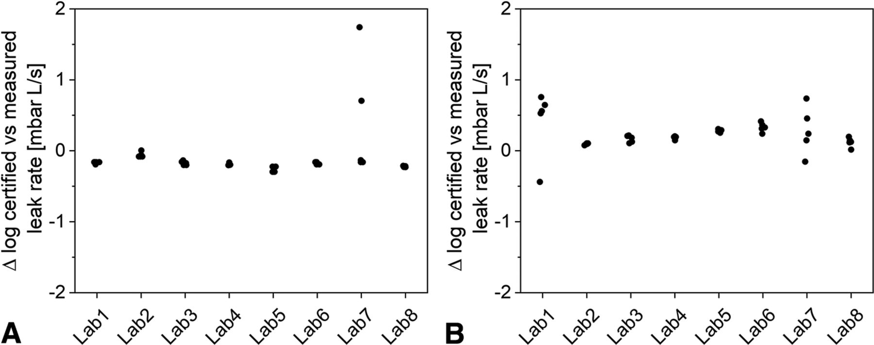
Two external He leak standards were measured in all participating laboratories, that is, a standard with a certified flow rate of 2.18E-04 and a second at 3.86E-08. Figure 2 represents the five measurement results per laboratory for both standards expressed as the difference of the respective result relative to the certified flow on a log scale. For the E-04 He flow standard, the achieved test results stayed within 1.0 log unit (n = 39 results) for all measurements except for one result of E-02 generated in laboratory No. 7. When treating this result as an outlier, a difference of −22% for the average value was obtained. In contrast, the test results of the E-08 standard showed overall a lower accuracy with a difference of 94% from the certified flow rate and a span of 1.20 log units (n = 40 results).

He leak standard measurements at different laboratories: (A) 2.18E-04, (B) 3.86E-08.
Linearity of He Leak Measurements
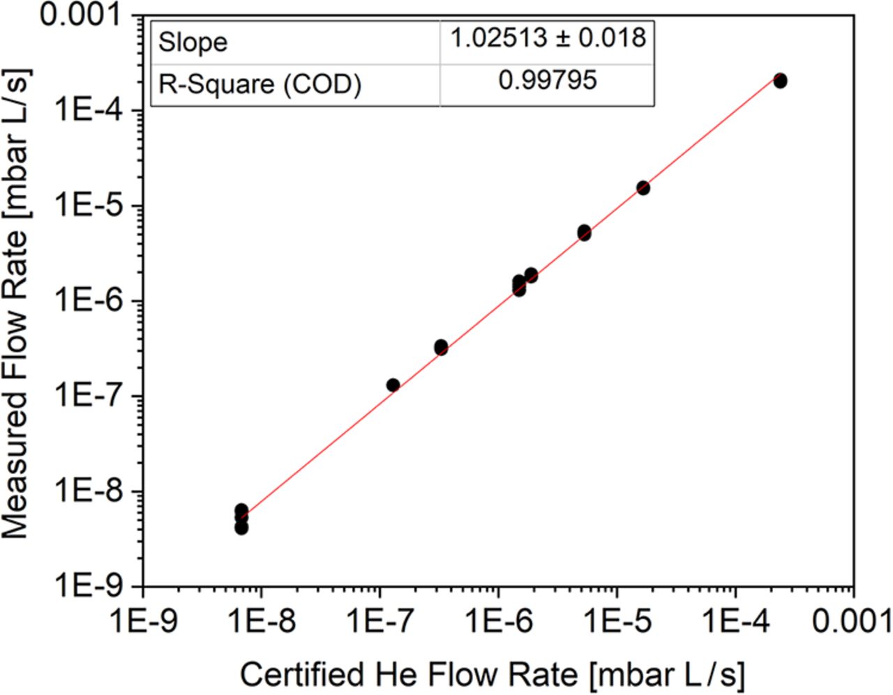
The results generated for the different certified He leak standards in the range of E-09 to E-04 can also be used to assess the linearity of the He leak method irrespective of the instrument type, measurement mode, and laboratory. The response was linear with an r-square of the certified vs. measured He flow rate of 0.998 over five orders of magnitude (Figure 3).

He flow rate measured vs. certified for He leak standards (n = 5 determinations per certified flow rate).
Assay Sensitivity—Negative Leakage Controls
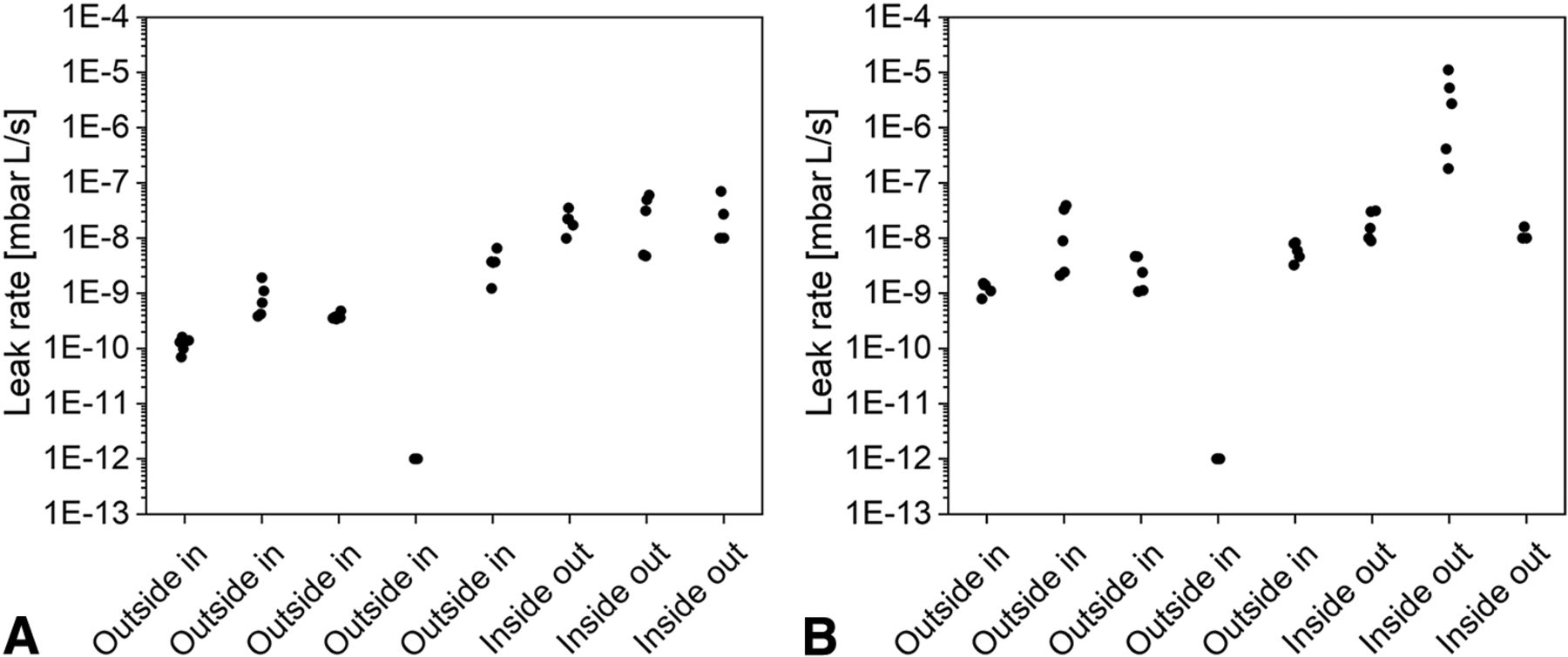
Negative controls, that is, nonleaking CCSs or surrogates for such CCSs (e.g., steel plug for a vial) allow assessment of the baseline level for He leak measurements in the actual method setup with sample chambers or fixtures in place and therefore evaluation of the lowest practically possible He leak rates. The results for vials across laboratories are displayed in Figure 4A; for syringes in Figure 4B for both measurement modes. For each replicate determination, the negative control unit was removed and installed again in the fixture or chamber. For the outside-in mode, He flow was present around the negative control while monitoring the flow rate. For the inside-out mode, the nonleaking test units were opened, filled with He (either flushed by a He gas-jet or introduced into a special hood flooded with He gas), closed again, and placed into the He leak test chamber for flow rate determinations.

Negative control sample results for vials (A) and syringes (B) from the five outside-in and the three inside-out mode test laboratories.
The fourth outside-in laboratory applied a baseline correction for low-level measurements that sets the output to E-12, and therefore this data set was not used for comparative data analysis. The remaining data from seven laboratories (n = 35 values per negative control vial and per negative control syringe) spanned a large range with values between 7.0E-11 and 1.1E-06 (span of 4.20 log units) for vials and from 7.9E-10 to 1.1E-05 (span of 4.14 log units) for syringes.
The overall large range over five orders of magnitude could mainly be attributed to the mode of measurement. On average, lower values were determined using the outside-in mode (1.3E-09, n = 20, four laboratories for vials) compared with the inside-out mode (1.3E-06, n = 15, three laboratories for syringes). The baseline values in the outside-in mode were comparable to negative control results of a larger set (n = 100 replicates) determined in one laboratory with an average of 4.3E-10 with a span of 0.35 (3.6E-10 to 8.0E-10). For comparison, the maximum values within the outside-in mode across the four laboratories was at 3.9E-08 (for syringes, Table III). In contrast, with the inside-out mode, values as high a 1.1E-05 were determined in one laboratory. These high leak rates of negative control samples measured with the inside-out mode may be attributed to the sample preparation, specifically the filling of the negative controls with He gas. Unexpectedly high results can be due to interferences by residual He adsorbed on the outer surfaces of the CCS. It is unlikely that the negative control units were leaking, because the containers were newly prepared using “fresh” closures between each determination. In general, adsorbed He gas residues on the outside of the CCS are a challenge when applying the inside-out method. A He desorption step during sample preparation is necessary and typically established. However, if such a desorption step is conducted for too long, this will significantly lower the accuracy of the inside-out method due to He gas depletion, because the limited amount of He gas effuses out of containers with a leak. Effusion of He gas is, in particular, a challenge for the inside-out test setup when measuring larger leaks in combination with small-volume containers (e.g., 1 mL syringes). Thorough method development including sample preparation is required for the inside-out method, and a compromise between adsorbed He gas on the outside of the container and sufficient He gas levels in the inside of the CCS needs to be accepted. Overall measurement artifacts are CCS and artificial leak size specific. It should be mentioned that filling the CCS with a jet of He gas instead of placing the entire unit in He gas atmosphere was effective in reducing the baseline levels for inside-out determinations with maximum reported values for negative controls at 7.0E-08.
Negative Control Sample Results
In summary, the baseline for He leak measurements in the outside-in mode was consistently below E-07 even for small-volume CCSs (i.e., 1 mL syringes), whereas in the inside-out mode, values as large as E-05 were reported, suggesting that He leak test methods need further refinements if used for small-volume containers (Figure 4). Negative controls should be part of the assay as a system suitability test (SST) to establish adequate performance of the He leak assay before any measurement.
Comparison between the Two Applied He Leak Measurement Modes
Besides the negative control samples, shared CCSs with artificially created leaks were measured with the outside-in and inside-out method in five and three participating laboratories, respectively. Not all shared artificial leak units could be measured by both methods, as the inside-out method requires filling of the CCS with He gas before measurement. Filling of the CCS with He gas, however, mandates the removal of the closure, which affects the performance and intrinsic properties of certain artificially prepared leaks such as wires inserted between rubber closures and the container wall. Of note, no participating inside-out testing laboratory had established a He gas filling step by piercing the rubber stopper with a needle connected to a He gas source and subsequent gluing of punctures before measurement.
For the remaining pool of shared CCSs, the averaged He flow rates were highly comparable overall, that is, within 0.5 log units, between both measurement modes (Table IV). In contrast, the spans of flow rates were not consistent between the two modes, not for a specific type of artificial leak, nor dependent on the nominal size. The outside-in mode resulted in wide individual He flow rate ranges (span up to 3 log units), for example, for the 2 µm laser-drilled hole in a vial or for the 0.2 µm glass micropipette inserted into a vial. The inside-out mode showed a higher range for a 10 µm laser-drilled hole in the syringe or in a vial, and for a 60 µm wire within the needle shield region of the syringe (span up to 5 log units). The largest deviations (from average values) were for both modes, always on the lower side, that is, toward He flow rates lower than average (see examples in Figures 6 and 7).

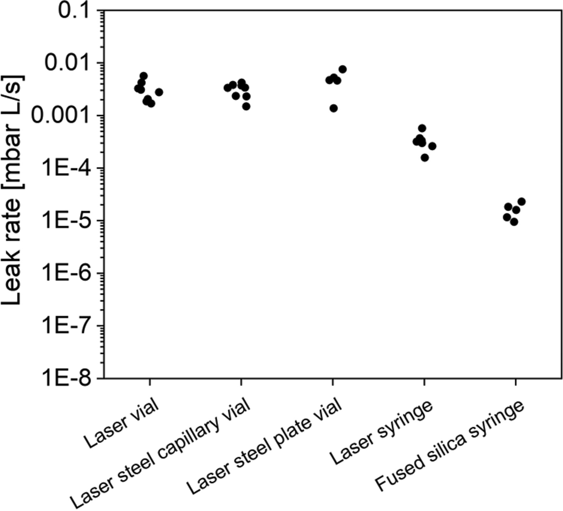
He flow rates for shared artificial leaks of equivalent 5 μm nominal size. Each dot represents the average measurement result for a laboratory.

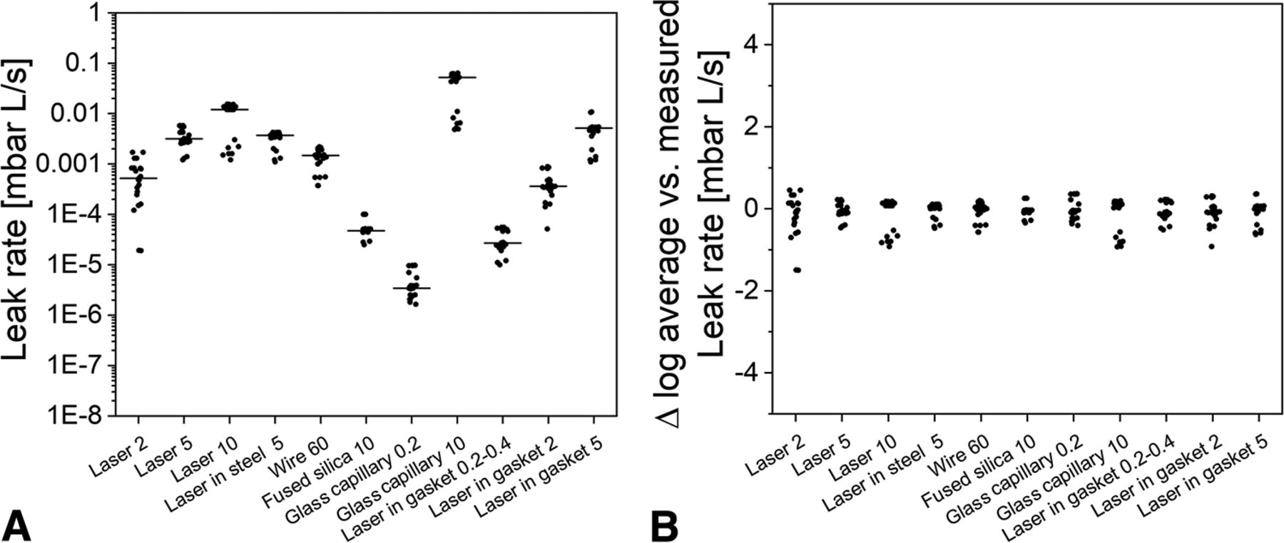
He flow rates for different types of shared artificial leaks in vials. (A) Each dot represents a single measurement result. The bar represents the average of measurements (five laboratories, five replicates in each laboratory). (B) Differences from the average He flow rate in log10 scale. Each dot represents a single measurement.

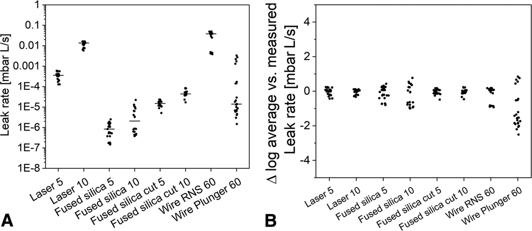
He flow rate results for shared artificial leaks in syringes. (A) Each dot represents a single measurement result. The bar represents the average of measurements (five laboratories, five replicates in each laboratory). (B) Differences from the average He flow rate in log10 scale. Each dot represents a single measurement.
Examples of Artificially Created Leak Results for the Two Applied He leak Measurement Modes
No fundamental differences were noticed and are expected between both measurement modes, but inside-out mode determinations were shown to be more error prone and difficult to handle for small-volume containers due to the impact of residually adsorbed He gas and the challenge of He gas depletion (see discussion on negative control results). Within this study, only a few small-volume CCSs (e.g., 1 mL syringes) with artificial leaks could be measured in the inside-out mode due to the necessity of He gas filling on shared CCSs in different laboratories.
Nominal Leak Size and Actual Leakage Rate
Artificially created leaks and assay sensitivity are frequently specified in terms of geometrical size, usually in micrometer terms. During this study, different artificial leaks with identical nominal leak sizes with micrometer scale were compared. Figure 5 shows five different artificial leaks, each with a nominal size of 5 µm. Comparable He flow rates were obtained for laser-drilled holes in the vial glass body (average: 3.1E-03, span 0.99, n = 40) or a steel tubing (average: 3.1E-03, span 0.58, n = 40) or laser-drilled holes in a steel orifice plate (average: 4.7E-03, span 0.99, n = 25), and in the glass body of a syringe (average: 3.3E-04, span 0.67, n = 39). Fused silica capillaries in syringes, with the equivalent nominal inner diameter of the capillary, did exhibit lower flow rates (average: 1.6E-05, span 0.66, n = 25) (Figure 5).
Other examples for 10 µm nominal sized leaks (Figure 6) showed similar trends, with the average measured He flow rates of the nominal 10 µm glass micropipette being at 3.4E-02, of a 10 µm laser-drilled hole at 9.1E-03, and of a 10 µm ID fused silica capillary at 5.4E-05. This can at least partially be explained by the shorter leak path in laser-drilled holes or glass micropipettes vs. fused silica capillaries.
In summary, the nominal geometrical leak size of an artificial leak does not describe correctly and unambiguously the leakage rate, as not only the nominal diameter, but also the length of the path, the internal geometry of the leak (e.g., tortuosity), and the presence of one or multiple channels (which can sometimes be observed for laser-drilled holes) impact the overall measured He flow rate. Preferably, artificial leaks could be characterized using the He flow rate measurements, and it can be of advantage to refer the size of artificial leaks and the CCIT method sensitivity to He flow rates. However, because a primary intention of any CCIT is to ensure the sterility of injectable drug products, it also needs to be taken into account that also the ingress of microorganisms into a container is strongly dependent on the leak path size and geometry and not only on actual gas flows (see discussion on acceptance criteria).
Precision of Outside-In He Leak Assay
Assay precision and some additional aspects of He leak measurements are summarized hereafter for the outside-in mode only because of the reduced number of containers with simulated defects that could be measured with the inside-out mode method as outlined before, as well as the higher variability observed for the baseline measurements of the negative controls as described previously.
Assay Repeatability in One Laboratory
Multiple measurements on the same instrument performed within a day by the same analyst showed very consistent He flow rates with a span of only 0.07 log units for an artificially created leak path in a vial using a 10 µm ID fused silica capillary (Table V).
Outside-In He Leak Measurements in One Laboratory
The assay variability was slightly higher when multiple units of equivalent vials, each prepared with fused silica capillary leaks or with laser-drilled holes in steel capillaries, were measured. A lower span of 0.10 log units with an average He flow rate of 7.3E-05 was obtained for 100 vials prepared, each with 10 µm ID fused silica capillaries at a length of approximately 12 mm (Table V). The span was higher for a 2 µm nominal laser-drilled hole with 0.50 log units despite the higher He flow rate of 8.2E-04. For larger nominal laser-drilled hole defects, the span was more comparable with 0.18 log units for a 10 µm (average flow rate at 3.3E-03) and 0.11 log units for a 20 µm (average flow rate at 1.6E-02) nominal laser-drilled hole. The assay precision can be estimated based on the span, which was ≤0.5 log units independent of the flow rate (E-02 to E-05, Table V).
Assay Reproducibility—Multicompany Study Results
The different shared test samples with all main types of artificially created leaks were measured in each laboratory according to each company’s established analytical test procedures. The nominal leak sizes ranged from 0.2 µm for glass micropipettes inserted into vials or laser-drilled into steel disks placed instead of a stopper onto a vial to 10 µm laser-drilled holes in vials or syringes. Larger orifices were not included in the study as larger leaks can generally easily be detected by the He leak technique but result quickly in very high He flow rates (e.g., 30 µm glass capillary around E-01) and subsequent memory effects necessitating long purge times to return to an adequately low baseline for sensitive measurements.
The variability of the measurements across all laboratories were within a span of 1.2 log units for most of the simulated defects in vials (Figure 6B) with average He flow rates between 3.3 E-05 and 1.0E-02 (Figure 6A). Two artificial leak samples showed higher variability mainly due to measurements in one laboratory resulting in an overall span of 2.5 log units for a 2 µm nominal laser-drilled hole and of 3.0 log units for a 0.2 µm glass capillary sample. When those results were omitted, the span of the remaining four laboratories would be within 1.2 log units.
Two nominally 0.2–0.4 µm sized defects were shared between the laboratories to measure the artificial leaks within the nominal size range frequently associated with the absence of a microbial contamination risk (3, 5). He flow rates between 9.6E-09 and 9.8E-06 (average 4.2E-06) were determined for the 0.2 µm glass micropipette and between 1.0E-05 and 5.5E-05 (average 3.3E-05) for the 0.2-0.4 µm stainless-steel orifice disks, both in vials (Figure 6). Two outliers were found with a He flow rate of ≤1.6E-08 in one laboratory (see also previously), for which the other three results were in the expected E-06 range, which can most likely be associated to a temporary blockage of the 0.2 µm glass micropipette.
In summary, for vials, no practically relevant differences with respect to assay variability were observed between the artificial leak types, that is, comparable spans of 1.2 log units for He flow rates between E-06 and E-02.
In addition, different prefilled syringe samples with artificial leaks were shared between the laboratories. Some of the shared units showed rapid blockage such as for 2 µm laser-drilled holes in the glass body or 20 µm sized wires within the needle shield. In other instances, reported manipulation errors such as nonremoval of the needle shield to allow passage of He gas prevented the use of all results. Nonetheless, the variability was generally similar to that of the vial artificial leak samples, with syringe measurement variability being slightly higher but still within 2 log units. Two outliers were observed with a first baseline value (E-09) for a 5 µm laser-drilled hole and 60 µm wire for the first replicate in a laboratory with subsequent flow rates in the expected ranges, indicating manipulation errors. Wires within the syringe plunger showed a notably higher span of 3.4 log units between laboratories, which may be due to small movements of the rubber stopper caused by the vacuum during replicate measurements resulting in dimensional changes of the flow path or due to silicone oil slightly changing the actual geometrical dimensions of the leak.
Discussion
The He leak method is currently the most sensitive CCIT method and preferably used for the initial CCS qualification and characterization studies. However, limited information is available in the public domain regarding the method performance parameters such as accuracy or precision, and differences between the two He leak measurement modes (“Inside-out”/“outside-in”). To the best of our knowledge, the study discussed in this article is the first broader CCI multicompany study performed within the pharmaceutical industry. Other multilaboratory CCI studies, for example, published by Wolf et al. (9), used a different CCI methodology (vacuum decay) and only featured a few participating laboratories (three) assessing one type of CCS (1 mL syringes), included limited artificial leak types and sizes (5-15 µm laser-drilled holes), and did not put the results into perspective regarding setting a holistic acceptance criteria for microbial tightness.
Key benefits of the study presented in this article are that two different He leak measurement modes were compared, and method performance parameters such as linearity, accuracy, precision, and baseline were characterized. Vials and syringes as well as all commonly used artificial leak types in a broad nominal size range of 0.2–60 µm were included, and eight different laboratories from major pharmaceutical companies were involved. The results underline that He leak testing allows appropriate characterization of leakage within a relevantly wide size range for the CCI evaluation of sterile products and characterization of artificial leaks.
Moreover, the observations of this multicompany study can help to set He leak test acceptance criteria and to elaborate adequate He leak method validation concepts.
Artificially Created Leaks
Geometrical size in terms of micrometers is frequently used to describe leaks and is conceptually easier to understand compared with more abstract parameters such as flow rates or leakage rates. However, different artificial leaks featuring the same nominal geometric size do not represent comparable leakages and He flow rates. In conclusion, describing a CCI method sensitivity by stating a simple nominal leak size is not appropriate without statement of the type of leak. As all CCI methodologies’ measurement principles are based on liquid or gas flow, the use of a He flow rate to describe the method sensitivity or to characterize the artificial leaks used during method validation allows a standardized comparison across laboratories, techniques, methods, and products.
For each type of artificial leak used, issues were reported in the course of the study, such as blockage and breakage during repetitive measurements. Finally, results for 85% of the shared vials and 70% of the shared syringes with simulated defects tested over 1 year in eight laboratories with multiple shipments could be used for data analysis and provided He flow rates in the expected ranges. Artificial leaks are delicate to handle and should ideally be verified before use, for example, when used for CCI assay validation activities.
Major characteristics of the different artificial leak types as observed during the studies are as follows:
Laser-Drilled Holes:
Laser-drilled holes in the container glass body were more delicate and prone to blockage compared with laser-drilled holes in metal (e.g., tubing or metal disks), which on the other hand have the drawback that they require additional manipulation (e.g., gluing or proper sealing). For equivalent nominal sizes, comparable He flow rates were observed for laser-drilled holes in glass, steel tubing, and steel disks (e.g., 5 µm results, Figure 5). However, some differences were observed between laser-drilled holes introduced into the glass body of vials and syringes (e.g., 5 µm nominal leak in vial with 3.1E-03 vs 3.3E-04 in syringe). Moreover, He flow rates might also differ when laser leaks from different suppliers or drilled with different laser equipment are used.
Wires:
The 60 µm wires do not result in the same He flow rate when inserted in different parts or location of a CCS, for example, within the needle shield (3.2E-02 on average) versus rubber plunger stopper (4.9E-04 on average) of a glass syringe and also versus the rubber stopper and glass part of a vial (1.4E-03 on average). This can be explained by the elasticity and relaxation properties of rubber components as well as the geometric properties. Repetitive measurements of the same unit with wires introduced in potentially moving parts such as the plunger rubber stopper of a syringe may be affected by small movements due to handling or exposure to the high vacuum of the He leak instrument. Therefore, those parts should be carefully locked before He leak measurements, and artificial leaks based on wires may not be used for repetitive measurements.
Glass Micropipettes:
The main advantage of glass micropipettes is that very small nominal sizes are commercially available. However, glass micropipettes are generally very delicate to handle during preparation and cannot be easily used in small containers (e.g., 1 mL syringes) due to geometric limitations. Therefore, glass micropipettes were only used in vials in this study. The vulnerability of glass micropipettes was demonstrated during this study by the pronounced increase of flow rates across repetitive measurements despite the protection of the fragile tip inside the glass vial. This once more shows the necessity to verify certified leak sizes prior to and after use in CCI tests, and to be extremely cautious when they are used in studies involving liquids.
Fused Silica Capillaries:
Fused silica capillaries were easy to prepare, they provide very consistent results within the laboratory, and their robustness was acceptable. However fused silica capillaries also clogged during the round-robin study and their length impacts flow rate. It should be mentioned that differences in capillary length (2–3 mm) of the same order as the thickness of typical glass vial or syringe walls (1–2 mm) cause differences in He flow rates of approx. 0.10 log unit well within assay variability (determined for ten 10 µm ID fused silica capillaries, for each given length the span was ≤0.03 log units). In general, the well-defined geometric shape of capillaries by internal diameter and length allows the calculation of theoretical leak rates (for gas and liquids see for example references 10⇓–12), if the pressure differential is known.
In summary, no artificial leak gold standard exists, and all commonly used methodologies (to create artificial leaks) feature both challenges and benefits. The nominal diameter (in micrometers) does not qualify to accurately describe a CCI method sensitivity, and different types of artificial leaks with the same nominal diameter can exhibit different gas and liquid flow rates. The actual gas flow rate more accurately describes a leak size; however, this is not directly connected to a microbial contamination risk as, for example, a pinhole of 0.2 µm may have the same flow rate as a longer artificial path length of a capillary with 10 µm internal diameter.
Development of a He Leak Acceptance Criteria for Microbial Tightness of a (Rigid) CCS
The development of a physical CCI (pCCI) method acceptance criteria for microbial tightness comprises two main steps. Firstly, the measurement results (method output) of a pCCI test must be related to a microbial contamination risk. Secondly, method performance parameters such as accuracy and precision must be characterized to evaluate if the method performance supports the desired limit.
Considerations for a He leak acceptance criteria or limit for microbial tightness are discussed hereafter and relate to the maximum allowable leakage limit (MALL) preventing microbial and liquid ingress or to the critical leak size (defect size at which loss of sterility is detectable). Other CCI method acceptance criteria, for example, CCIT to find a gross leak and major assembly defects or the ability of a CCS to maintain a gas headspace exist but are out of scope of this article.
USP <1207> (4) provides recommendations on how to establish an acceptance criterion for microbial ingress:
“experimental indirect or direct comparison of the microbial ingress risk (or liquid leakage risk) to physicochemical leak test method capability” whenever “method's limit of detection is notably greater than the maximum allowable leakage limit”.
When applying a MALL of <6E-06 (He flow rate) or an orifice of a nominal 0.1–0.3 µm diameter as a limit, USP <1207> (4) considers that there is no need for an experimental microbial ingress (mCCI) or liquid challenge study as a function of leak size. In other words, He leak CCI methods with their proven evidence of detecting critical leak sizes below this MALL do not need a correlation study, at least for rigid CCSs. For other, more complex CCSs or methods with a different sensitivity, a study exploring the relationship between defect size and type and the risk for microbial or liquid ingress may be helpful unless published correlations are available or other theoretical considerations justifiable.
The previously cited correlation of zero microbial ingress risk with <6E-06 He flow rate and 0.1–0.3 µm orifice size is based on a published study by Kirsch et al.iv (3). Other published pCCI – mCCI correlation studies (Table VI), which included leaks showing no (zero) microbial ingress, showed more variable cutoffs for microbial tightness depending on study conditions and artificial leaks. Morrical et al. (5) established a zero ingress for wires inserted between vial and rubber closure of 15 µm OD corresponding to 1.3E-05 He flow rate or a stainless-steel orifice of 2 µm with 1.4E-03 He flow rate. Mathaes et al. (13) described a limit of 4E-07 for different wires in rubber stoppers, which is two orders of magnitude lower than the criteria established by Morrical. Burrell et al. (14) determined a cutoff value for microbial tightness for 5 µm ID fused silica capillaries of 3 cm length corresponding to 3.7E-06 He flow rate. Keller and colleagues (15, 16) did not detect any loss of sterility under various conditions with nickel microtubes of 7 mm length and a diameter of 2 µm corresponding to a He flowrate 3.1E-07. Critical leak size was determined by bioaerosol challenge tests for air-filled defects to be approximately 7 µm for pressure differentials ranging from 0 to −34.5 kPa (17). Infiltration of pathogens or spoilage organisms through various defect types was determined for leakage rates between 2.0E-06 and 6.1E-03, whereas zero ingress was in the range of 2.2E-07 to 1.4E-03 He flow rates under studied conditions. As defects are only available in discreate sizes, for example, a 2 µm ID capillary followed by a 5 µm ID, the actual cutoff could be between those two sizes (Table VI).
Correlation Studies
Microbial contamination and microbial ingress into a CCS only occurs if the following sequence of events happens: that is, microorganisms need to be in close proximity to the leak or breach orifice of the CCS, the leak/defect needs to be filled with liquid, and the microorganisms need to “travel” through the liquid-filled leak path into the inner compartment of the CCS by their own motility or more likely after initiation of liquid flow driven by, for example, pressure differential or capillary forces. In addition, the liquid flow rate needs to exceed the evaporation rate (17) and microorganisms need to grow within the CCS. The liquid flow and its initiation are a function of the leak size and path, the surface tension/viscosity of the liquid in the leak, and importantly the pressure differential between inside and outside of the CCS. Interestingly, Keller et al. (15) could not detect microbial ingress through a ≤20 µm sized nickel capillary of 7 mm length (capillaries of this dimension show typically a He flow rate of 1.1E-03) when no pressure differential was applied, even at airborne microorganism concentration of 106 cells/cm3 in a bioaerosol-generated microbial ingress study using three different microorganisms. A wide range of leak sizes between 5 and 200 µm (Table VI) was experimentally determined by Ravishankar et al. (18) for the entry of E. aerogenes into trays filled with tryptic soy broth with yeast extract, beef enchilada, and chicken, and it was concluded that not only the establishment of a fluid bridge between inside and outside is necessary, but also the ability of the inner substrate to support the entry and survival of any ingressed microorganisms impacts the critical leak size. The variability may also be due to plugging of pinhole leaks by viscous, inhomogeneous content and by the tendency for enlargement of hole diameter in plastic lids due to treatment.
Overall, not only the defect dimensions and type of artificial leak or corresponding leakage rate (e.g., expressed as He flow rate) may impact the critical leak size or MALL but also the experimental conditions such as pressure differential, surface tension, and viscosity of the liquid/media and the position of the defect, that is, in contact with product liquid or with head space only (defect filled with liquid or air). This explains the different limits for microbial contamination in terms of He flow rates or defect sizes reported in the literature.
Based on experience with sterile filtration and microbiological challenge studies, a 0.2/0.22 µm-rated filter (19) can be considered a safe limit for retention of microorganisms from passing through a barrier or a CCS under multiple conditions and consequently preventing microbial contamination of a CCS. Similar to CCIT, in the well-established area of sterile filtration, it is well understood that pore size rating is not sufficient, and that, for example, the shape of the porous structure and adsorptive retentivity of filters were also stated as critical factors in the retention of particles/microorganisms (19).
Artificial leaks in the relevant size range were measured during this collaborative study and showed for 0.2 µm glass micropipettes an average He flow rate of 5.6E-06 with an upper measured rate at 1.0E-05 (n = 38 results, eight laboratories), and for a nominal 0.3 µm laser-drilled orifice in a steel plate an average rate of 3.3E-05 with a maximum at 5.5E-05 (n = 25 results, five laboratories). The latter is comparable to the He flow rate of 4.3 to 5.6E-05 determined in a single laboratory for 0.4 µm glass micropipettes.
The study results confirmed that He leak method performance parameters do support such a limit across multiple laboratories. All laboratories accurately measured He leak standards with a certified He flow rate at E-04 and E-08. The He leak method also produced linear results between E-09 and E-04 across the laboratories. The precision for artificial leaks in the relevant low micrometer-size range was acceptable with a span of ≤1.5 log unit. Negative leakage control measurements for vials and syringes were in the vast majority at least one to two orders of magnitude lower than this limit, that is, on average at 5.9E-08 (n = 65 results, disregarding the results from Laboratory 6 for syringes). However, the fact that in some instances He flow rates for tight CCSs were close to or even exceeded the suggested limit for microbial ingress emphasizes the importance of including negative control units at least during method development and qualification.
It is suggested to use for rigid container closure systems a conservative acceptance criterion for He leak measurements at for example 6E-06 when excluding contributions by interfering He gas permeation or multiple additive nanometer pores. This limit covers most of the mCCI and pCCI correlation studies and is in the relevant range confirmed by this collaborative study.
Validation of the He Leak Method for Good Manufacturing Practices (GMP) Measurements
The He leak method can be operated as a quantitative test. In this case, a He flow rate is reported. Alternatively, the method can also be applied as a limit test with an associated pass/fail criterion for a predefined He flow limit, such as the MALL or other justified limits.
For characterization purposes, for example, CCS qualification, a quantitative test is suggested. A numerical flow rate allows an in-depth characterization of the CCS and the evaluation of the criticality of a potential leak. Characterization studies during CCS development do not require a validated GMP method. The use of appropriate SST is sufficient to demonstrate the acceptability of measured He flow rates.
In contrast, a quantitative test offers no benefits compared with a limit test during routine CCI GMP testing of a well-developed product container for human use. During routine GMP testing, the product container is tested against a defined specification (limit). Method validation is required for GMP testing.
ICH Topic Q2 (R1) Validation of Analytical Procedures: Text and Methodology defines the purpose of analytical method validation as the following:
“The objective of validation of an analytical procedure is to demonstrate that it is suitable for its intended purpose.”
In the following practical aspects of a He leak method, the validation strategy is described following ICH Q2 (R1) principles and industry best practices. Additional procedures to assess method performance, which are typically applied in combination product development as described in, for example, ISO 17025:2017 and ISO 5725-1 to 6 are referenced in brief but not discussed in detail. The He leak method validation is performed on a CCS-specific basis and not on a product-specific basis, unless a specific product property impacts the performance of the method. In general, it is preferred to perform all validation activities using artificially created leak samples in the specific CCS to evaluate the entire CCIT system including the sample holder. If no artificial leak samples are available for specific validation activities, alternative strategies have to be developed, for example, using certified flow standards.
Accuracy:
CCSs with robust and accurate flow-certified artificial leak are not commercially available for an entire CCIT system validation. Therefore, He leak method accuracy can only be assessed by measuring certified He leak standards and consequently, once performed for a system, is valid for different CCS/product containers. The accuracy assessment should be performed using certified He leak standards in a range covering or bracketing the specification. During this study, certified He leak standards over a range of E-09 to E-04 did show an accuracy of ±50% across different labs. Shared E-08 He leak standard, however, showed a difference of 94% with a span of 1.2 log units. These measurements suggest an acceptance criterion of ±50% of the certified flow rate for larger flow rates and an acceptance criterion of ±150% of the certified flow rate for very small flow rates (<≈E-07). Of note, accuracy assessment during analytical method validation is typically performed over short time periods. Our accuracy assessment represents a worst-case scenario, as the measurements were performed over a 1-year time frame in different labs by different operators with He leak standards not optimized for the specific instrument type.
Linearity:
The results obtained from the accuracy assessment can be used to establish linearity. In this study, the response was linear with a r-square of the certified vs. measured He flow rate of 0.998 over 5 orders of magnitude in flow rate (E-09 to E-04).
Precision:
The He leak method precision (analysis not system) and intermediate precision or reproducibility can be evaluated using artificial leaks. A typical sample size is n = 6 independent replicates for precision and two times n = 6 for intermediate precision. Artificial leaks should be chosen to cover He flow rates above and below the specification. In case artificial leaks are not available with a He leak flow rate below the specification, He leak standards must be used. However, using He leak standards is not preferable as the He leak system including the sample holders should represent the measurement setup used during GMP testing. In our study, the established method variability of different artificial leaks was within laboratory 0.5 log units, across laboratories in most instances 1.2 log units (independent of the leak rate, E-2 down to E-5). The highest deviations were toward lower than average He flow rates. We suggest acceptance criteria during He leak method validation for analysis precision of 0.5 log units and for reproducibility of 1.5 log units. Of note, a gage R&R according to ISO 5725 may be performed during method validation for combination product GMP testing.
Robustness:
Method robustness is typically assessed during late-phase clinical development or prior commercial GMP testing. The criticality of deliberate changes of certain method parameters (e.g., room temperature, instrument warm-up time, dimensions of O-rings or relevant CCS diameter “extremes”, He flow rate in outside-in mode or He concentration in inside-out mode) is assessed. If specific method parameters show an impact on method performance, these method parameters have to be controlled more tightly during routine measurements.
Limit of Quantification (LoQ):
Defining the LoQ of the He leak method is challenging. As mentioned previously, accurate and robust CCSs and more importantly artificial leaks are not (commercially) available at the method LoQ. Secondly, baseline measurements at very low He flow rates of <E-09 may show drift during consecutive measurements, which represents a challenge when applying typical procedures (e.g., USP <1225>) to assess the method LoQ. Using certified flow standards at, for example, E-9 or preferably the use of long small-bore capillaries (≤2 µm ID) to create artificial leaks at very low flow rates are possible practical approaches to establish the method LoQ. He leak standards alone will, however, neglect contributions due to the sample and test chamber such as permeation through CCS materials or sealing rings.
Specificity:
The He leak methodology with the mass spectrometry detector features an inherent specificity to He gas. No practically relevant interference was observed, and He gas is only present in traces in the atmosphere (approximately 5 ppm). Therefore, specificity is typically not assessed.
Range:
The method range can be defined after assessment of accuracy, linearity, precision, LoQ, and robustness. The method is expected to show adequate performance of the complete range of the method. As described previously, the two most challenging aspects are showing method precision below the proposed MALL and establishing method LoQ.
In summary, the validation of the He leak method for GMP testing as a quantitative flow-rate method is not straightforward; artificial leak samples and certified flow standards as well as acceptance criteria have to be carefully chosen. Nevertheless, the previously mentioned procedure represents a robust strategy. For most purposes, a limit test with reduced method validation parameters may be preferred for GMP testing for CCIT.
Based on the robust and consistent performance of the He leak method throughout the multicompany study, we propose a lean and practical approach to method validation.
The He leak method has shown consistent accuracy and linearity when challenged with certified He leak standards. These standards are CCS independent as no sample holder is used. Additionally, accuracy is preferably confirmed during instrument qualification and by an SST before each measurement series using at least one He leak standard close to the requested limit. Therefore, we suggest performing accuracy and linearity assessments only once for the specific instrument by measuring multiple certified He leak standards without validating these parameters again during CCS-specific validations. Specificity can also be excluded from validation experiments given the inherent selectivity of the mass spectrometry detector for He gas. Precision (assay, intermediate or reproducibility) should be part of a CCS validation. In order to bracket the acceptance criteria, low He flow rates intact (nonleaking) samples and different artificially prepared leaks inserted in the specific CCS may be used. All intact samples should yield flow rates at least 1 log unit below the acceptance criteria.
Conclusion
The He leak method is currently the most sensitive CCIT method and preferably used for the initial CCS qualification and characterization studies. Within the pharmaceutical industry, several He leakage CCIT methodologies exist, including different instrumentation, measurement, or implementation of system suitability control samples.
The current study holistically characterized the impact of test methodology specifics. The He leak method was found to be sensitive to assess reliably the integrity of CCSs even below the MALL of E-6.
Both measurement principles (outside-in and inside-out) were found to provide acceptable test results. However, the inside-out method was less versatile, not capable of precisely measuring large leaks or even allowing repeated measurements during precision assessments for some samples as well as being prone to measurement artifacts resulting from He adsorption for negative controls.
The method performance (e.g., accuracy, intermediate precision) was assessed by the variability of He leak rate results. He leak rate results were described to be within 1.5 log across laboratories, container types, and artificial leak types.
The results of the He leak method performance assessment were used to define a robust He leak method validation strategy and acceptance criteria.
The current study aimed to assess variations in test results across the industry when applying company-specific He leak test methodologies and represents worst-case but real-life application. As a follow-up study, we suggest performing a well-designed, round-robin study with predefined and harmonized test method parameters to evaluate a best-case multi-laboratory scenario.
Conflict of Interest Declaration
The authors declare that they have no competing interests.
Acknowledgments
The authors would like to acknowledge the following people who contributed to the development, He leak measurements, or review of this work: Maria Maier, Karen Neuhold, Janssen R&D; Luis Sanchez, Martin Vogt, Lonza AG; Sabrina Flakenbach, Silke Sattler, Bianka Stiefenhoefer, AbbVie; Tomas Burock, Stefano Cannavo, Eva-Maria Müller, Sanofi; Helen Brown, Holger Röhl, Henrik Steinberg, F. Hoffmann-La Roche; Verena Geidobler, Lukas Mühlfeld, Bernd Fluhr, Boehringer Ingelheim Pharma GmbH&Co; Antonia Saraceno, Giacomo Storti, Novartis; Joerg Zürcher, Bayer AG, Michael Molitor, CSL Behring, and Jane Polliti, Merck.
Footnotes
- © PDA, Inc. 2022


