
Abstract
For steam sterilization load validation of porous/hard goods loads, regulatory guidelines state to identify and validate the worst-case challenge that is the most difficult to sterilize. The maximum load and the minimum load are usually considered as worst-case challenges, and both are validated. This article demonstrated with examples how the control strategy determined the worst-case load in the steam sterilizer. It further established with examples how a suitably designed control strategy could nullify the impact of varying load characteristics (e.g., mass, configuration, and air removal challenges) in porous/hard goods loads and make it load size independent.
Introduction
It is a common practice across the pharmaceutical industry to identify and validate the maximum load and minimum load for operational feasibility. The maximum load is considered as the worst-case challenge in terms of a large number of items and subsequent air removal challenge. The minimum load is considered as the worst-case challenge in terms of air removal, and it can receive lower heat input compared with the maximum load.
As indicated in PDA TR01 (1), “For the cycles which do not have fixed heat up and cool down rates/times, the minimum load receives lower thermal input than maximum loads and should also be challenged.” In this case, along with the maximum load, the minimum load is also the worst-case challenge and needs to be identified and qualified. Three successful consecutive biological qualification runs are required to be qualified for both maximum load and minimum load.
Cycle development control strategies were elaborated by James Agalloco in an article published in February 2018 titled “Maximum and Minimum Loads in Steam Sterilization” (2). In this, Agalloco explained the control strategies depending on the equipment capabilities/capacities and the requirement of maximum and minimum load validation for each control strategy. This case study further builds on the control strategy presented by Agalloco with actual load examples. The conclusion of this article recommends a control strategy that will provide adequate time for air removal and heating irrespective of the load size.
Materials and Methods
The tools and techniques used in this case study are explained in the following sections;
The Test Equipment (Sterilizer)
All the runs were performed in a Fedegari Autoclave code number NA1861AS. The autoclave had a double door design. The chamber volume of the autoclave was 1075 L.
The probes used for temperature measurement/control: PT 100 (Elsi srl)
The probes used for pressure measurement/control: TP 1 (Baumer)
The external thermocouples (TCs) used for temperature measurement: all temperature measurements in the autoclave were performed by placing type “T” TCs in the load items. All TCs were calibrated to have ±0.5°C accuracy. All temperature data was logged by using the Yokogawa data logger (model GP10, Serial number: S5T209668).
Test Items (Load)
The autoclave loads used for demonstration were as follows.
Load Type 1: Garment load
The maximum for the Garment Load will be referred to as “Max Load 1”
The minimum for the Garment load will be referred to as “Min Load 1”
Load Type 2: Mixed load (including filters connected to pressure vessels, silicon tubes, etc.)
The maximum for the mixed load will be referred to as “Max Load 2”
The minimum for mixed load will be referred to as “Min Load 2”
The load items for these loads are detailed in Tables I⇓⇓⇓⇓–IV. The autoclave loads followed the fixed item fixed position approach. Every item had a defined position on the tray/stand in the autoclave. The required items were wrapped in bacterial barrier bags to ensure steam penetration. The items were oriented for maximum steam exposure and to facilitate quick condensate removal. The TCs were placed in the test items in multiple locations to map temperature. The TCs were placed such that the tips of the TCs did not contact the surfaces of the items. Also, the TCs were oriented to avoid condensate accumulation on the tips. Additionally, it was ensured that the TCs did not interfere with the integrity of the wrapping materials or inhibit the flow of steam inside the test items.
Load Item Details “Max Load 1”
Load Item Details “Min Load 1”
Load Item Details “Max Load 2”
Load Item Details “Min Load 2”
Test Design
The loads were sterilized using the following control strategy:
Prepulsing with a predefined pressure end point, positive pressure gradient, and negative pressure gradient, i.e., the increase and decrease of pressure was controlled by ramping/dropping the pressure at a defined rate (in mbar/sec). There was a defined vacuum hold after every pulse.
Heating with a predefined positive pressure gradient (in mbar/sec) to achieve the desired temperature set point.
This controlled ramping/dropping of the pressure and temperature during the prepulsing and heating phases was achieved by automated modulating action of the steam supply valve to maintain the desired set points.
The rationale for selecting the control strategy was as follows:
The rate of steam addition and vacuum drawing was defined. Hence, the time for the steam injection and vacuum drawing were expected to be same theoretically. Additional vacuum hold after every pulse was defined. This provided an adequate time for air removal and preconditioning of the load.
The rate of steam addition was defined during the heating phase prior to the sterilization hold phase. Hence, the items were expected to get the same heat input irrespective of the load size.
The recipe used for the control strategy is detailed in Table V and Table VI. Three runs of the maximum load and three runs of the minimum load were executed for both load types. Biological indicators were not used for performing the runs executed in this study. These shall be used for actual validation runs of each load, as per respective protocols and guidelines (3) (4) (5).
Recipe Used for the Garment Load
Recipe Used for Mixed Load
Results and Observations
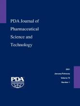
The equilibration times for both the garment loads and the mixed loads (maximum as well as minimum runs) were well below the acceptance criteria of 30 s (for all cycles the equilibration time observed was zero seconds). For all the runs, the minimum Fo (lethality) of 30 min was obtained at all the thermocouple locations. The time required for the prevacuum pulsing phase and heating phase is detailed in Tables VII and VIII. Representative cycle outputs: the cycle output for a mixed load, one maximum load and one minimum load is presented in Figures 1–4. It was theoretically expected that both the time for steam injection and the time for vacuum drawing would be the same irrespective of the load size, because the modulated heating and modulated vacuum rate were defined in the recipe. The data showed that the time for steam injection was the same irrespective of the load size with modulated heating. However, there was a difference in the time required for vacuum drawing even with the use of a modulated vacuum rate. However, this was compensated by the addition of a vacuum hold phase after every pulse of 3 min (Load Type 1) or 4 min (Load Type 2). The length of this hold phase was established from the average difference (Load Type 1)/maximum difference (Load Type 2) in air/steam removal time between the maximum and minimum loads for the load type. This ensured that the load items in the autoclave have enough time for air removal irrespective of the number of items in the load.

Pressure versus time graph—example from “Max Load 2”. Run progressive number: 20,254; program start time: 31.01.2020 11:35:14; program end time: 31.01.2020 13:48:21.

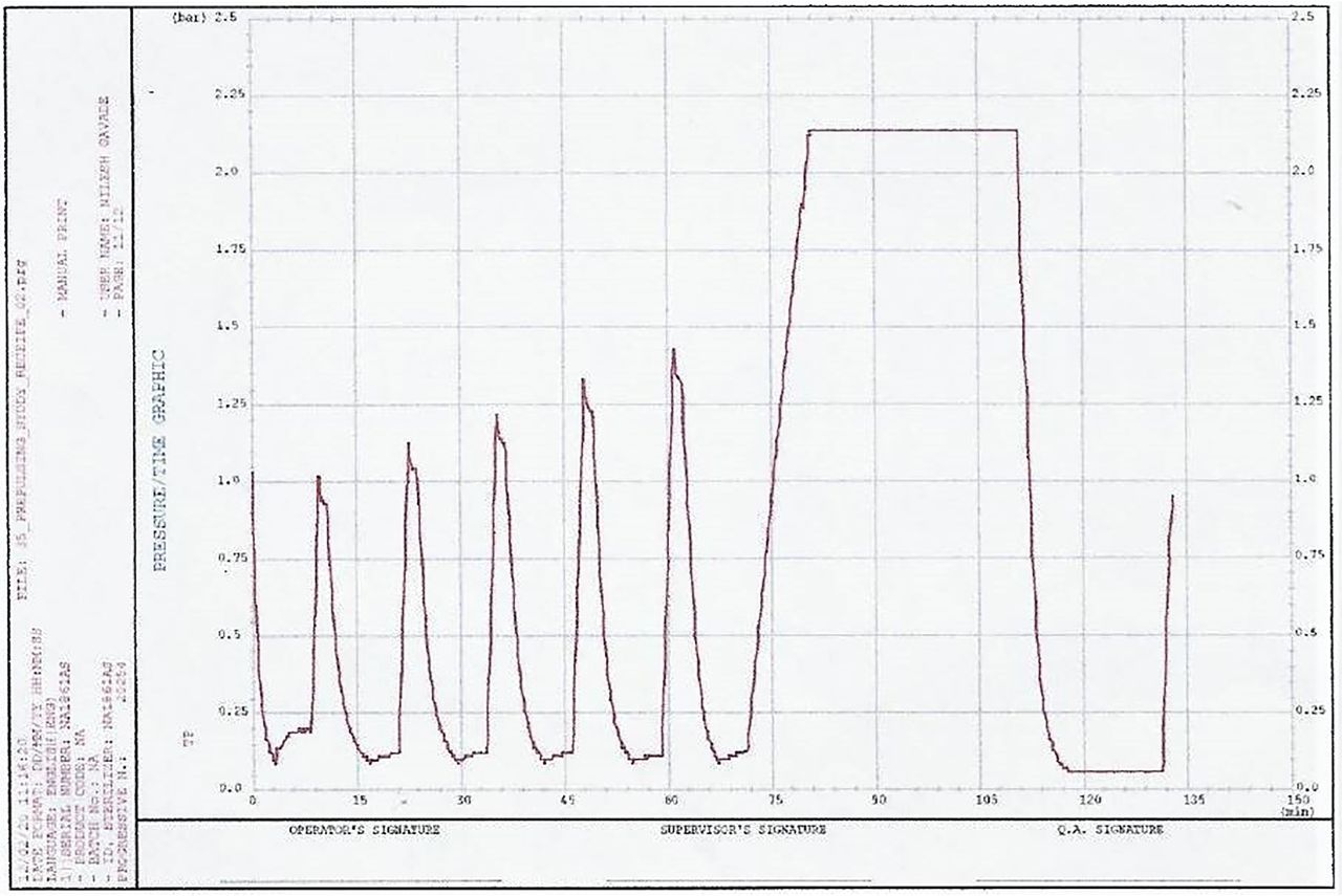
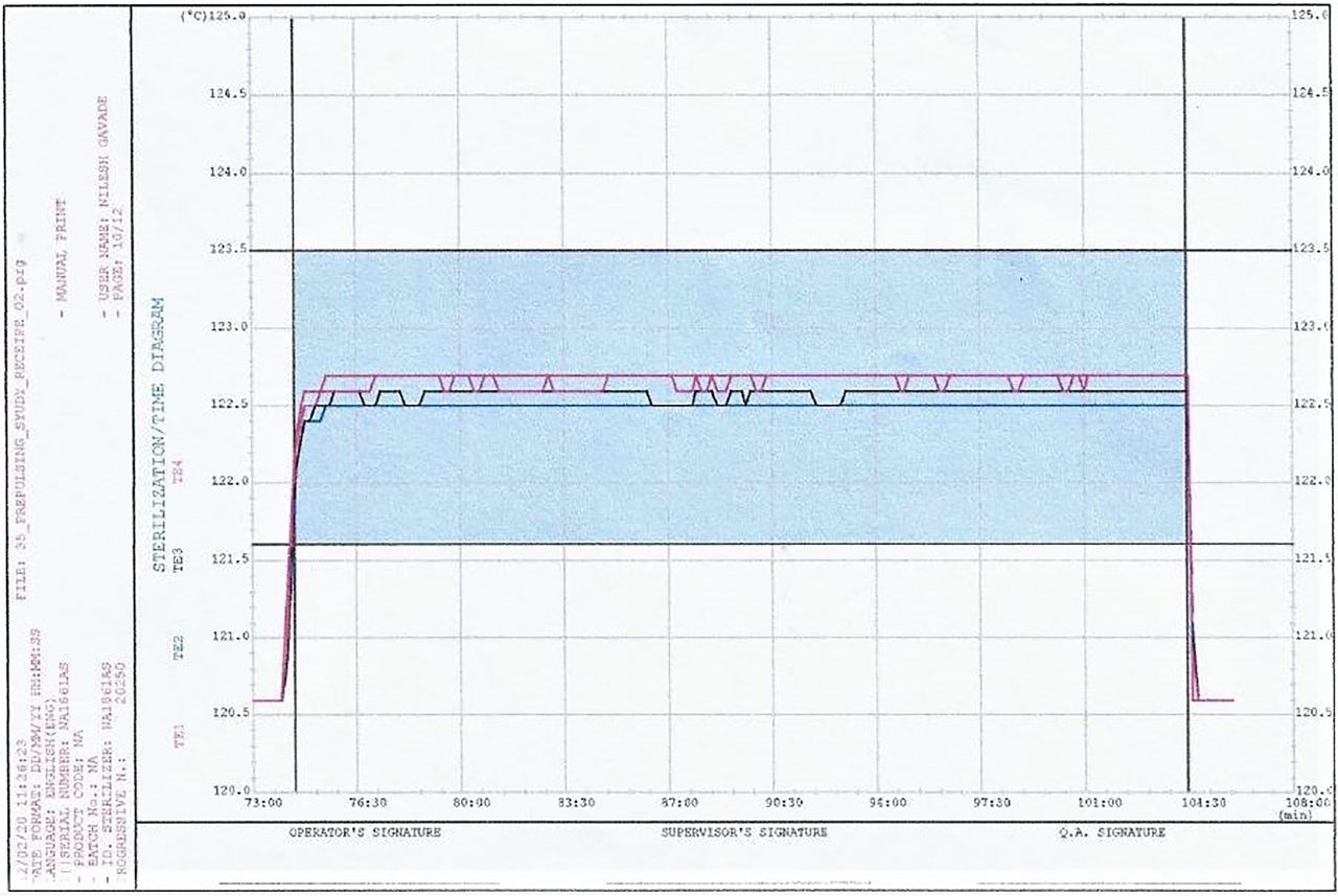
Temperature during sterile hold—example from “Max Load 2”. Run progressive number: 20,254; program start time: 31.01.2020 11:35:14; program end time: 31.01.2020 13:48:21.

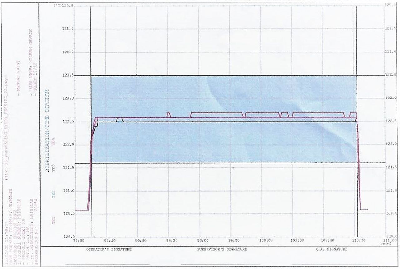
Pressure versus time graph—example from “Min Load 2”. Run progressive number: 20,250; program start time: 30.01.2020 16:02:00; program end time: 30.01.2020 18:07:14.

Temperature during sterile hold—example from “Min Load 2”. Run progressive number: 20,250; program start time: 30.01.2020 16:02:00; program end time: 30.01.2020 18:07:14.
Prepulsing (Steam Addition and Air Removal) Time and Heating Time for “Max Load 1” and “Min Load 1”
Prepulsing (Steam Addition and Air Removal) Time and Heating Time for “Max Load 2” and “Min Load 2”
During the heating phase before the sterile hold phase, the time required to achieve the sterilization temperature was almost the same in the case of both the maximum and minimum loads for both load types because of the modulated steam injection rate. This ensured that the items in the load received the same thermal input irrespective of the load size.
Conclusion
Based on the data the following conclusions were drawn:
Conclusion 1
During the prepulsing phase (preconditioning phase), an adequate steam injection time and air removal time was ensured by using modulated steam injection and modulated vacuum rates.
Steam injection time: by using the modulated steam injection rate, the heating time/steam injection time was independent of the load size.
Air removal time: it was theoretically expected that by using a modulated vacuum rate, the time required would be the same for the maximum and minimum loads. However, the data showed that there was a difference between the air/steam removal times for the maximum load and the minimum load. The time for air/steam removal for the maximum load and minimum load would be the same only if the rate of air/steam removal from the porous/hard goods loads was not the rate limiting step. However, the data from the runs showed that the rate of air/steam removal was actually affected at some points in both the garment loads and the mixed loads. As a result, there was a significant difference between the times of air/steam removal for the maximum and minimum loads.
It is also seen that during the pre-pulsing phase, the defined rate of vacuum draw, i.e., 20 mbar/2 sec was not always maintained. This was because at the end of the vacuum draw, the rate decreased for both the maximum and minimum loads. This rate of decrease at the end of the vacuum draw was significantly less for the maximum loads. And this was the primary reason why the air/steam removal times were significantly different for the maximum and minimum loads. As a result, the maximum load received more time for air removal compared with the minimum load. This was compensated by the addition of 3 min/4 min vacuum hold after every pulse. This additional time will ensure effective air removal for minimum as well as maximum loads.
Conclusion 2
Heating phase (prior to sterilization hold phase): by using a modulated steam injection rate, the heating time was made independent of the load size.
Hence it was concluded that for the current control strategy, the heating time was by design made independent of the load size. Also, additional vacuum hold was provided after every modulated vacuum phase to provide extra time for air removal for the “minimum load”. Therefore, only the maximum load was the worst case and needs to be validated. As per the PDA TR01 (1) bracketing approach, the current control strategy is “single ended bracket”
Recommendations
Based on the conclusions, the following recommendations were made for porous/hard goods loads:
Recommendation 1
For the prepulsing phase: use a modulated rate for steam injection and a modulated vacuum rate for air removal. An additional vacuum hold step after every pulse was recommended so that the items in the autoclave will get adequate time for air removal irrespective of the load size.
Recommendation 2
For the heating phase: use a modulated steam injection rate so that the articles will get the same thermal input irrespective of the load size.
Based on the data, it is recommended that this control strategy should be the preferred strategy for porous/hard goods load validation. This strategy provides enough time for air removal and heating irrespective of the load size. This will ensure that the load is equilibrated and effective sterilization is achieved because the air removal is effective. The recipe/cycle design should be done as per the following chronology:
Step 1: Run the maximum load development cycle with a modulated prepulsing and a modulated heating phase.
Step 2: Run the minimum load development cycle with the same modulated prepulsing and heating phase.
Step 3: Calculate the maximum difference in air removal time between the maximum and minimum loads. Add the time difference as the vacuum hold after each pulse. (Adding the maximum air removal time as the vacuum hold would be ideal. In this case, study one example as detailed considering the average time difference [garment load] and one example as detailed considering maximum time difference [mixed load]).
Step 4: Validate the maximum load (three consecutive successful runs) with modulated prepulsing (with vacuum hold after every pulse) and modulated heating phase.
Step 5: Perform one verification/confirmation run with the minimum load.
Loads shall be considered validated upon successful completion of the above runs with biological challenge and meeting all other sterilization acceptance criteria as per respective protocol and guidelines.
Conflict of Interest Declaration
The authors declare that they have no competing interests. All authors of this manuscript certify that they have read and approved this manuscript.
Acknowledgements
We thank the persons on the shop floor for their support in the execution of the runs that generated the data discussed in this paper.
- © PDA, Inc. 2021


