
Abstract
Syringe filling of high-concentration/viscosity monoclonal antibody formulations is a complex process that is not fully understood. This study, which builds on a previous investigation that used a bench-top syringe filling unit to examine formulation drying at the filling nozzle tip and subsequent nozzle clogging, further explores the impact of formulation–nozzle material interactions on formulation drying and nozzle clogging. Syringe-filling nozzles made of glass, stainless steel, or plastic (polypropylene, silicone, and Teflon®), which represent a full range of materials with hydrophilic and hydrophobic properties as quantified by contact angle measurements, were used to fill liquids of different viscosity, including a high-concentration monoclonal antibody formulation. Compared with hydrophilic nozzles, hydrophobic nozzles offered two unique features that discouraged formulation drying and nozzle clogging: (1) the liquid formulation is more likely to be withdrawn into the hydrophobic nozzle under the same suck-back conditions, and (2) the residual liquid film left on the nozzle wall when using high suck-back settings settles to form a liquid plug away from the hydrophobic nozzle tip. Making the tip of the nozzle hydrophobic (silicone-coating on glass and Teflon-coating stainless steel) could achieve the same suck-back performance as plastic nozzles. This study demonstrated that using hydrophobic nozzles are most effective in reducing the risk of nozzle clogging by drying of high-concentration monoclonal antibody formulation during extended nozzle idle time in a large-scale filling facility and environment.
LAY ABSTRACT: Syringe filling is a well-established manufacturing process and has been implemented by numerous contract manufacturing organizations and biopharmaceutical companies. However, its technical details and associated critical process parameters are rarely published. Information on high-concentration/viscosity formulation filling is particularly lacking. This study is the continuation of a previous investigation with a focus on understanding the impact of nozzle material on the suck-back function of liquid formulations. The findings identified the most critical parameter—nozzle material hydrophobicity—in alleviating formulation drying at the nozzle tip and eventually limiting the occurrence of nozzle clogging during the filling process. The outcomes of this study will benefit scientists and engineers who develop pre-filled syringe products by providing a better understanding of high-concentration formulation filling principles and challenges.
- Prefilled syringe
- High-concentration monoclonal antibody
- Suck-back
- Hydrophilic nozzles
- Hydrophobic nozzles
- Nozzle clogging
Introduction
We previously reported an investigation of parameters that are critical for high-concentration (HC) monoclonal antibody (mAb) formulation filling using a bench-top filling model (1). In that study, glass nozzles and a high-speed camera were used to visualize liquid suck-back (SB) behaviors and performance in relation to peristaltic pump parameters and filling nozzle size. Stainless steel nozzles are widely used for sterile filling, but unfortunately they are not transparent and cannot be visualized to assess SB performance. The correlation between optimal SB with a decreased rate of formulation drying at the nozzle tip and decreased tendency of nozzle clogging were clearly demonstrated in that study. Optimal SB only occurred in a narrow SB operating range based on visualization from glass nozzles.
This study aimed to continue building the body of knowledge regarding HC mAb formulation syringe filling by providing insight into the impact of formulation and nozzle materials on SB behaviors/performance. A wide range of nozzle materials, including plastic, were investigated. Plastic nozzles can be part of disposable filling lines currently emerging as a preferred facility design strategy (2, 3). Plastic materials, including polypropylene, silicone, and Teflon®, are common interfaces with drug products in pharmaceutical applications for liquid transfer and container closure. The transparent nature of these materials enables visualization during the filling process and offers an advantage for evaluation in this study. More importantly, these plastic materials are more hydrophobic than glass and stainless steel based on contact angle data of water (4⇓⇓–7). Thus, all of these materials rendered a wide range of hydrophilic and hydrophobic surfaces to assess liquids within a broad range of viscosity, including water (1 cP), a mAb formulation (9 cP), and a 60% (w/w) sucrose solution (60 cP).
Finally, this study provides insight into the conditions that lead to nozzle clogging from the perspective of formulation type, concentration, and environmental conditions, thereby providing scientists and engineers who develop pre-filled syringe products with a deeper understanding of HC formulation filling principles and challenges.
Materials and Methods
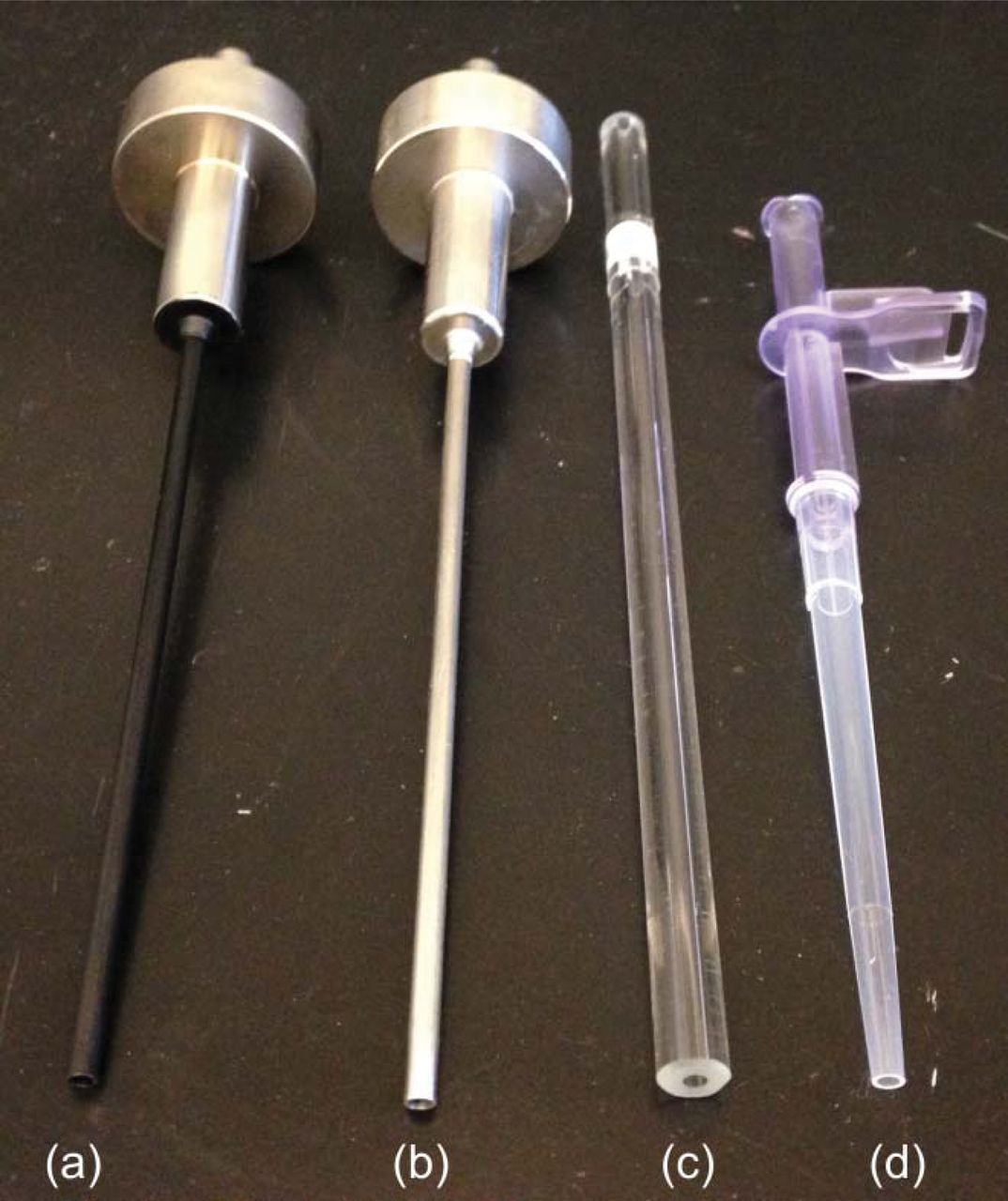
All experiments in this study used purified water, a mAb formulation (mAb at 200 mg/mL produced at Genentech Inc., South San Francisco, CA), or a sucrose solution (60% w/w). The mAb formulation contained histidine acetate, arginine acetate, and polysorbate 20 at pH 6.0. These liquids were filled into 25 mL polyethylene terephthalate (PETG) bottles (Thermo Fisher Scientific Inc., Waltham, Ma) via different types of filling nozzles using a bench-top filling system. Filling nozzles used in this study included (1) INOVA stainless steel nozzles (2.0 mm internal diameter [ID]; 90 mm long) from Optima Pharma GmbH (Schwäbisch Hall, Germany); (2) Teflon-coated stainless steel nozzles (Figure 1a) manufactured by SPC Manufacturing (Rillieux-La-Pape, France); (3) glass nozzles (2.0 mm and 3.0 mm ID; 90 mm long) obtained from Pegasus Industrial Specialties Inc. (Cambridge, Ontario, Canada); (4) polypropylene nozzles (2.0 mm tip ID) procured from Genentech/Roche; and 5) Teflon tubing (2.0 mm and 3.2 mm ID) by Optima Pharma GmbH.

Photograph of filling nozzles: (a) Teflon-coated stainless steel nozzle, (b) stainless steel nozzle, (c) glass nozzle, and (d) polypropylene nozzle.
Bench-top Filling System
A Flexicon PD12 peristaltic pump system controlled by a Flexicon MC12 control unit (Watson-Marlow Flexicon, Ringsted, Denmark) was used for filling. The setup for the peristaltic pump system has been previously described (1).
Siliconization of Glass Filling Nozzles
A 35% silicone emulsion (Dow Corning, Midland, MI) was pumped through 2.0 mm glass filling nozzles using the bench-top filling system. The glass filling nozzle was allowed to drip-dry for 30 min in order to clear out the emulsion from the interior of the glass filling nozzle. Air was also blown through the glass filling nozzle to further remove any excess silicone. The siliconized filling nozzles were then baked in a depyrogenation oven (LCD1-51-4, Despatch Industries, Minneapolis, MN) for 90 min at 300 °C. Glass powder coating was used to visually confirm that the silicone was evenly coated and baked onto the interior surface of the glass nozzles.
Teflon and Siliconized Glass Surfaces for Contact Angle Measurements
Several layers of polytetrafluoroethylene (PTFE) thread seal tape (Johnstone Supply, Portland, OR) were taped onto a plain glass side to create a flat, “Teflon” surface for contact angle measurements. To make a siliconized glass surface for contact angle measurements, a 35% silicone emulsion was spread on top of a plain glass slide three times. The glass slide was allowed to drip-dry for 30 min after each layer in order to remove excess silicone. The siliconized glass slide was then baked in a depyrogenation oven for 90 min at 300 °C. Glass powder coating was used to visually confirm that the glass slide was evenly coated with silicone.
Filling Operation and Experiments
The bench-top filling system was placed on a lab bench top at ambient temperature and a relative humidity of 40–50%. The pump parameters were set at 200 rpm and 50 acceleration for a fill volume of 1 mL per dispense. Interruption (or drying) studies and SB measurements were performed, using methods similar to what had been performed for a previously published article (1). Two millimeter ID stainless steel, Teflon-coated stainless steel, glass, siliconized glass, and polypropylene filling nozzles were tested in the interruption studies, and SB volumes in glass filling nozzles and Teflon tubing of various sizes (inner diameters) were measured.
Fluid (Formulation) Characterizations
I. Viscosity Measurement:
The method for measuring viscosity has been previously described (1).
II. Contact Angle Measurement:
The contact angle of a fluid was measured by visualizing a 3.5 μL sample droplet on a stainless steel, Teflon, or siliconized glass surface using a microscope (Vertex 320, Micro-Vu, Windsor, CA) and a prism-shaped mirror. The mirror was used to reflect a side angle view of the droplet on the surface, and this image was captured using the built in camera of the microscope. The resulting images were analyzed in ImageJ (National Institutes of Health, Bethesda, MD) in order to measure the contact angle.
Results and Discussion
We previously reported filling nozzle clogging as the result of the drying of HC mAb formulation at the tip of the nozzle (1). To better understand the nozzle clogging phenomenon, this study investigated liquid-nozzle material interactions, that is, the inherent property of hydrophilicity and hydrophobicity at the liquid–nozzle interface.
Suck-Back (SB) Pattern of Tapered Polypropylene versus Straight Glass and Stainless Steel Nozzles
SB experiments were initially performed on the mAb formulation (200 mg/mL with a viscosity of 9 cP) using three 2.0-mm nozzles: a stainless steel nozzle, a glass nozzle, and a polypropylene nozzle (Figure 1). The polypropylene nozzle has a gradual tapering shape, while the shape of the glass and the stainless steel nozzles is straight. A 180 min drying experiment was performed on the mAb formulation in all three nozzles at different SB settings (SB0 to SB3). Liquid was dispensed at 15, 30, 60, and 180 min to observe if the nozzle was clogged. The results shown in Table I (results for the Teflon-coated stainless steel nozzle the and silicone-coated glass nozzle will be discussed later) suggested that the glass nozzle is most likely to be clogged in 15 or 30 min at all SB settings, while the polypropylene nozzle is least likely to clog (no clogging after 180 min). The stainless steel nozzle is also easy to clog within 30 min at all SB settings except for SB2 (clogged at 60 min). The presence of an optimal SB setting (i.e., a narrow SB range) for stainless steel and glass nozzles is consistent with previous findings (1).
Time for mAb Formulation Drying (Nozzle Clogging) in 2.0 mm Nozzles of Various Materials in Response to Suck-back Settings
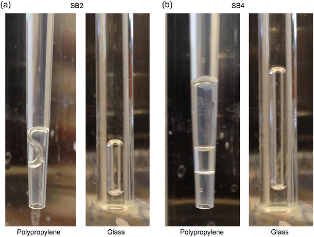
The SB pattern of the mAb formulation in the glass and the plastic nozzles was visualized with a camera. Interestingly, different SB patterns were observed: a liquid plug accumulated at the tip of the glass nozzle versus a liquid plug floating between the nozzle tip and the meniscus of the sucked-back liquid in the plastic nozzle (Figure 2). The delay of formulation drying and subsequent nozzle clogging in the polypropylene nozzle may be attributed to this unique SB pattern where the liquid plug formed away from the nozzle tip. Inside the nozzle, air flow becomes stagnant and the rate of water evaporation slows down. Based on these initial results, two likely root causes for the unique SB pattern were identified: (1) the tapering shape and (2) the interfacial properties between the liquid and the nozzle material.

Suck-back (SB) pattern of the mAb formulation in polypropylene and glass nozzles at different settings: (a) SB2 and (b) SB4.
Investigating the Effect of the Shape Factor Using a Glass Pipette
In order to evaluate whether or not filling nozzle shape alone could result in the unique SB pattern observed with the tapered polypropylene nozzles, the SB pattern of the mAb formulation at different SB settings was evaluated in glass pipettes with sharp, tapering tips (Figure 3a for 1 mm ID tip and Figure 3b for 2 mm ID tip). The data suggested that the air bubble created by SB at the tip tended to rise up, which was particularly true in the cases of narrow tip opening (1 mm ID) and large air bubble (high SB settings). At the tip region (sharp tapering) the shape of the air bubble was not uniform (deformed), so the bubble moved to a zone where the pressure is lower to form a more uniform bubble shape. As the bubble moved up, the pipette tip was filled with liquid. This observation indicated that a nozzle with a tapering tip may actually discourage a “clean” SB pattern (i.e., the absence of a liquid plug at the nozzle tip), and that shape was likely not a large contributor toward the SB pattern observed in the tapered polypropylene nozzles.
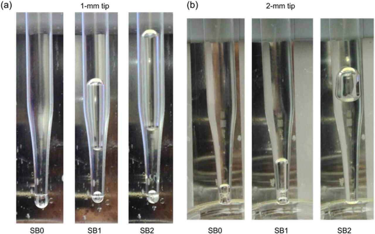
Suck-back (SB) pattern of the mAb formulation in a glass pipette with (a) 1 mm ID tip and (b) 2 mm ID tip at various SB settings.
Investigating the Effect of Nozzle Material Hydrophobicity on Suck-back (SB) Behaviors
In order to evaluate the effect of the interfacial relationship between the filling nozzle material and formulation, SB behavior in different substrate materials of differing hydrophobicity were evaluated. Hydrophilicity and hydrophobicity are often termed to interpret the interactions between a liquid and its substrate (nozzle material). The substrate surface is hydrophilic if a hydrophilic liquid (e.g., water) tends to spread over it, whereas with a hydrophobic surface a hydrophilic liquid tends to reduce its surface area of contact. Contact angle can conveniently quantify hydrophilicity and hydrophobicity of the substrate. This study assessed five substrate materials: glass, stainless steel, three plastics (polypropylene, silicone, and Teflon), and three liquids (purified water, a mAb formulation, and a 60% sucrose solution) to understand the impact of nozzle material hydrophobicity on SB behavior. Table II summarizes the contact angle measurements and liquid viscosity data for the materials and liquids assessed in this investigation. The increasing contact angle of water, going from on glass (<20°), stainless steel (68°), and plastics (97–122°) suggested that the glass surface is the most hydrophilic and that all three plastics are hydrophobic. Among the three plastic materials, Teflon appears to be most hydrophobic. The contact angle of the mAb formulation was lower than that of water on all substrates, due perhaps to the presence of surfactant (polysorbate 20) and surface properties of the protein, while the contact angle of the 60% sucrose solution was comparable to that of water.
Solution Viscosity and Contact Angle Measurements of Various Nozzle Materials
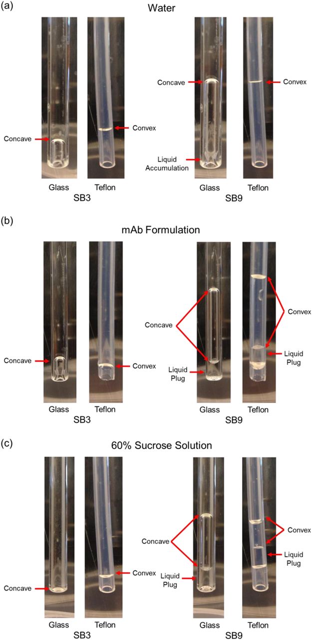
To verify the effect of surface hydrophobicity, the SB behaviors of all three liquids in a glass nozzle (3.0 mm ID) and a piece of Teflon tubing (3.2 mm ID) were visually compared at various SB settings. Figure 4 shows the photographs highlighting SB performance at a low SB setting (SB3) and a high SB setting (SB9). For water (Figure 4a), no liquid plug was observed in either nozzle, except for a slight accumulation of water at the tip of the glass nozzle at the high SB setting. For the more viscous mAb formulation (Figure 4b), neither nozzle showed a liquid plug at SB3. Although a liquid plug was formed at SB9 in both nozzles, it is located at the nozzle tip for the glass nozzle and within the tip for the Teflon nozzle. To suck back the most viscous sucrose solution (Figure 4c), SB3 could barely withdraw the liquid into the glass nozzle and only slightly into the Teflon nozzle. At SB9, a liquid plug formed in both nozzles with the same pattern as previously observed—at the tip of the glass nozzle and away from the tip of the Teflon nozzle. The SB behavior for the three different liquids at SB9 for both nozzles was repeatedly tested and found to be reproducible. The results confirmed that at high SB, a liquid plug tends to form at the tip of a hydrophilic nozzle but stays away from the tip of a hydrophobic nozzle.

Suck-back/meniscus pattern of (a) water, (b) mAb formulation, and (c) 60% sucrose solution in glass and Teflon nozzles at SB3 and SB9.
Another observation also confirmed the hydrophobic nature of the Teflon nozzle: its convex meniscus versus the concave meniscus of the glass nozzle (indicated in Figure 4). A convex meniscus occurs when liquid molecules have a stronger attraction to each other (cohesion) than to the material of the container (adhesion) (7), that is, liquid retreating from the Teflon surface. A liquid whose molecules have a stronger attraction to the material of the container than to each other forms a concave meniscus, that is, the liquid climbing up the glass surface.
The relationship of SB volume and SB setting for all three liquids is presented in Figure 5. The trend of higher SB volume in response to lower viscosity was consistent with previous findings (1). The Teflon nozzle resulted in a slightly larger SB volume than the glass nozzle, suggesting that the hydrophobic surface promoted liquid SB.
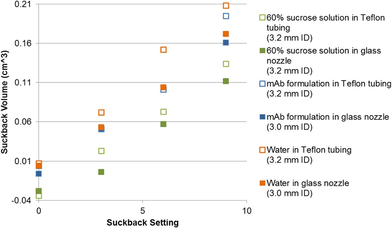
Suck-back volume of water, mAb formulation, and 60% sucrose solution in glass and Teflon nozzles in response to SB setting (SB0, SB3, SB6, and SB9).
Effect of Liquid Viscosity and Nozzle Material Hydrophobicity on Liquid Plug Formation
The formation of a liquid plug in the filling nozzle depended on the thickness of the liquid film on the inner surface of the nozzle. The liquid film thickness depended on liquid viscosity; the more viscous liquids left a thicker film. For example, in the case of water (Figure 4a) at the high SB setting (the worst case), the amount of water accumulated at the tip of the glass nozzle was too small to form a liquid plug. However, for the more viscous mAb formulation and the 60% sucrose solution, a liquid plug formed and its volume increased as the liquids were sucked back.
The formation of a liquid plug at different locations in the nozzle can be explained by capillary action, which represents a force balance between the cohesive force of the liquid (surface tension), the adhesive force between the liquid and the nozzle material, and the force of gravity. The liquid film left on the internal surface of a hydrophilic nozzle initially remained intact upon SB. However, the film began to flow down due to gravity and stopped at the nozzle tip due to surface tension and adhesive force. In a hydrophobic nozzle, the film quickly contracted toward between the nozzle tip and the meniscus of the sucked-back liquid because the liquid will resist association with the hydrophobic surface. The final location of the liquid plug was balanced by the force of gravity and the uplifting repulsive force of the hydrophobic surface below the liquid plug.
Relationship of Nozzle Material Hydrophobicity and Nozzle Clogging
Based on the observations of the effect of nozzle material hydrophobicity on SB behavior, it was hypothesized that the material of the hydrophobic nozzle tip plays a dominant role in slowing down formulation drying and nozzle clogging due to surface interactions between the liquid and the nozzle material. This hypothesis was further confirmed by expanding the 180 min drying experiment to include two new hydrophobic nozzles (Teflon-coated stainless steel [Figure 1a] and siliconized glass) (Table I). As predicted, the behavior of the drug product formulation in the Teflon-coated stainless steel and siliconized glass nozzles mimicked the behavior of the previously tested polypropylene nozzle. No clogging was observed for most SBs after drying for 3 h, compared with the hydrophilic nozzles (stainless steel and glass), which were completely clogged within 30 min.
The extended drying time can be largely attributed to the differences in SB behavior noted earlier. However, even when a liquid droplet was formed at the tip of a hydrophobic nozzle and dried after an extended interruption, no clogging was observed (Table I). This observation can also likely be attributed to the nozzle material's hydrophobicity. A liquid plug at the tip of a hydrophobic nozzle is less likely to completely clog the nozzle since the liquid plug is less likely to firmly adhere to a hydrophobic nozzle surface compared to a hydrophilic nozzle.
Relationship of Formulation Composition and Nozzle Clogging
For nozzle clogging to occur, the front edge of the formulation in the nozzle has to be dried, hardened, and firmly attached to the nozzle surface. Nozzle clogging is unlikely if any one of the three events does not occur. Dehydration (water evaporation) of the formulation front edge should take place during filling process interruption, typically less than 1 h. In addition to environmental conditions (temperature, humidity, air flow, etc.) and nozzle material hydrophobicity, the drying rate of a liquid can be affected by the composition of the formulation as well.
When a drop of the mAb formulation (200 mg/mL) and the 60% sucrose solution were left to dry on a stainless steel plate for up to 24 h, the mAb formulation dried faster (in 3 h) than the sucrose solution (in 24 h) (Figure 6). Other than a slower drying rate, during the history of drying, the surface of the drop of the sucrose solution turned viscous and sticky, but it remained in the liquid form. On the contrary, the surface of the drop of the mAb formulation turned to a dried crust quickly. It has been reported that upon spray drying, the droplets of sugar-rich solutions are sticky and tend to stick to the dryer wall or collide with each other to form undesired agglomerates (8, 9), whereas the droplets of mAb formulations are not sticky in the drying chamber of the spray dryer and can be effectively collected (10). However, as expected, the stickiness of the mAb droplets increased after an increasing amount of sugar was added to the mAb formulation (10). It can be hypothesized that the mAb formulation easily forms a dry crust at the air–liquid interface, which gradually thickens and turns into a hardened mass upon further water evaporation. The nozzle will not clog if the hardened mass can be dislodged under the pressure of pump dispensing, or in other words, the dry material is not firmly attached to the nozzle material.
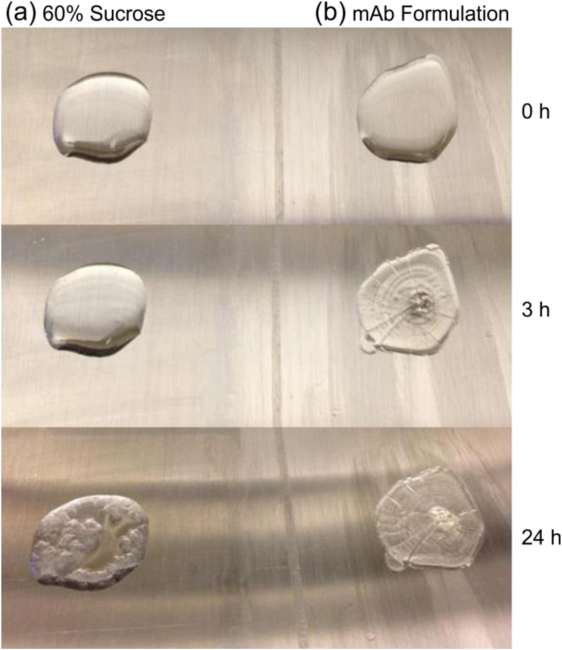
Drying behavior of a liquid drop of (a) 60% sucrose solution and (b) mAb formulation on a stainless steel sheet as a function of time (T = 0, 3, and 24 h).
Conclusion
This study identified nozzle material's hydrophilicity and hydrophobicity as the most important factors governing formulation drying and clogging at the tip of the filling nozzle. Hydrophobic nozzles allow the liquid plug to form away from the nozzle tip, which slows down formulation drying rates. Even if the liquid is not sufficiently sucked back (i.e., leaving a drop at the nozzle tip), the dried mass can be easily dislodged at the tip of the hydrophobic nozzle without clogging. Unlike the hydrophilic nozzles, which can only slow down formulation drying within a narrow range of SB conditions, the hydrophobic nozzles add significant operation flexibility to the manufacturing process of filling HC, high-viscosity mAb formulations. This study provides valuable insight into the conditions that lead to nozzle clogging and enables scientists and engineers who develop pre-filled syringe products to better understand the principles and challenges of HC formulation filling. It also supports a general understanding that nozzle clogging is more likely to occur in the case of filling HC polymer solutions under favorable drying conditions.
Conflict of Interest Declaration
The authors declare that they have no competing interests.
Acknowledgements
We are indebted to the support from Jacek Guzowski and Aaron Hubbard of Genentech for designing and installing the bench-top filling unit. We also thank Devon Roshan-Eisner for developing the contact angle measurement method.
- © PDA, Inc. 2015


Jump to section
Related Articles
Cited By...
- Mechanistic Study of Drying Phenomena of Highly Concentrated Protein Therapeutics--Drying Kinetics and Protein Aggregation
- Low-Volume Aseptic Filling Using a Linear Peristaltic Pump
- Filling of High-Concentration Monoclonal Antibody Formulations: Investigating Underlying Mechanisms That Affect Precision of Low-Volume Fill by Peristaltic Pump