
Abstract
We developed several techniques for visualizing the fit between a stopper and a vial in the critical flange area, a location typically hidden from view. Using these tools, it is possible to identify surfaces involved in forming the initial seal immediately after stopper insertion. We present examples illustrating important design elements that can contribute to forming a robust primary package. These techniques can also be used for component screening by facilitating the identification of combinations that do not fit well together so that they can be eliminated early in the selection process.
Introduction
Vial and stopper manufacturers generally do not collaborate to provide their respective customers with recommended matching configurations. Each pharmaceutical company must select vials and stoppers so that the complete primary package provides a robust barrier between the contents of the package and the external environment. To minimize incompatibility between stoppers and vials, manufacturers have adopted standard geometries for off-the-shelf parts. These components have physical attributes that adhere to recommendations set by the International Organization for Standardization (ISO), the Deusche Industrie Norm (DIN), and the Glass Packaging Institute (GPI) (1–3). However, the standard specifications for the dimensions of parenteral primary packaging components do not describe the mating surfaces with enough detail to guarantee proper mechanical function of the complete container/closure system. Even in engineering drawings, which include critical dimensions (stopper plug diameter, vial bore diameter, etc.), the shapes shown on paper are not sufficiently representative of the actual parts to properly assess performance of the sealing surfaces. Vials and stoppers that do not fit together properly will not provide a robust seal.
It is generally accepted that, after application of the aluminum crimp, the most reliable long-term sealing surface is formed by the top finish of the vial and the bottom of the stopper flange. However, in lyophilization applications, where stoppered vials may not be sent to the capper immediately after cycle completion, having a robust seal even prior to crimp sealing is critical in order to maintain the prescribed level of vacuum in the vials. Such is also the case for any products, liquid or powder, that require the presence of an inert gas headspace. Container integrity must be maintained by the seal formed in the region where the stopper plug is compressed by the vial bore. Previously, Morton (4) has pointed out issues related to leaks in packages prior to crimp sealing, but to our knowledge, there has not been a report specifically focused on assessing the effects of stopper–vial interactions during this critical period. This may be due to difficulties in observing the regions of interest.
In this communication, we describe techniques for evaluating how well stoppers and vials fit together by visualizing critical sealing surfaces normally hidden by the vial flange. This should not be confused with testing for container/closure integrity and microbial ingress discussed in numerous literature reports (5–10). Rather, the methods we present are tools, useful during the initial screening stage of component selection, for troubleshooting problems in existing components, or for designing custom vial and stopper combinations.
Materials and Methods
Packaging Components
All stoppers and vials were purchased from major suppliers to the pharmaceutical industry, conform to the GPI or ISO specifications for parenteral packages, and are in use by pharmaceutical companies for products marketed in the United States, Europe, and Japan.
Vial Profiles
Due to the strong curvature and restricted access, it is difficult to directly observe the interior surfaces in a vial neck and flange. To facilitate this task, sections of interest were removed from vials with a rotary tile saw equipped with a wet cutting diamond blade. These vial sections were embedded in Dow Corning SYLGARD® 184, a low-shrinkage, two-part silicone elastomer. After full cure, the vial segments were carefully removed from the silicone block, leaving a negative imprint. The transparent silicone block was cut with a new razor blade to obtain sharp, square edges. The exposed surface was then rendered hydrophilic by using a corona surface treater (Electro-Technic Products, Inc.). This allowed the profiles of the imprinted vial segments to be highlighted by a black permanent marker (see Figure 1).High-contrast images of the casts were recorded with a stereomicroscope equipped with a digital camera; magnification was measured with a stage micrometer. Vial profiles were created by processing the images with CorelTRACE.
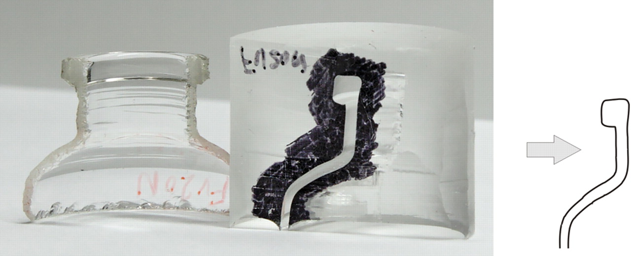
Vial profile from casting with elastomer. The image shows a section of a vial neck, its cast, and the profile obtained by processing the image with CorelTRACE®.
Stopper Profiles
Stoppers were photographed with a stereomicroscope equipped with a digital camera. The optical axis of the camera was perpendicular to the vertical axis of the stopper to minimize perspective distortions. The stopper profiles were created by processing the images with CorelTRACE.
Stopper and Vial Assembly Imaging
Extreme lensing effects caused by the shape of the vial neck and flange prevent direct observation of a stopper plug once it is inserted into the vial. To reduce the optical distortions from the curved glass surfaces, we adapted the strategy used for oil immersion microscopy. The vial under study was filled with silicone oil or mineral oil, each of which has a refractive index close to that of glass. Then the stopper was inserted, and the vial was immersed in a rectangular transparent container filled with the same oil. The interface between the vial and stopper was photographed with a Canon 5D digital camera equipped with a 180-mm macro lens. Lighting was adjusted to enhance edge contrast.
Stopper rubber swells slowly as it absorbs the oil. However, this effect is negligible during the time frame of the experiment.
Results and Discussion
The files containing profiles of stoppers and vials were imported into Corel Draw. Adobe Illustrator or other computer-aided design (CAD) software also could be used for this purpose. Because the magnification of each image was known, we were able to normalize each profile to a common scale, enabling direct comparison between any vials or stoppers.
The potential for mechanical interaction can easily be evaluated by superimposing vial and stopper profiles. Any overlapping regions indicate an interference fit, where the stopper plug is larger than the vial bore. A seal is created after the stopper is inserted into the vial if the elastomer is compressed sufficiently against the glass in the vial bore region above the blowback. The amount of overlap required for a secure seal depends on the shapes of the complementary surfaces and the durometer of the elastomer. Excessive overlap may make it difficult to insert stoppers fully, while insufficient overlap may result in a weak seal.
Blowback design and the design of corresponding features on stoppers can also have a major influence on the mechanical interaction between these components. Vials with an American blowback style, Figure 2a, have a groove in the neck bore about 1.5 mm below the finish. The European blowback style, Figure 2b, widens the groove to include the entire lower portion of the neck (the blowback style names are historical artifacts and no longer refer to the origin of the components). The blowback is intended to engage certain features on the stopper and provide enhanced functionality. For instance, a no-pop ring on a serum or lyophilization stopper can nest in the blowback to maintain the stopper in the fully seated position. For lyophilization applications, the blowback also engages the lower nibs of the stopper to prevent it from falling off the vial while in the vent position.
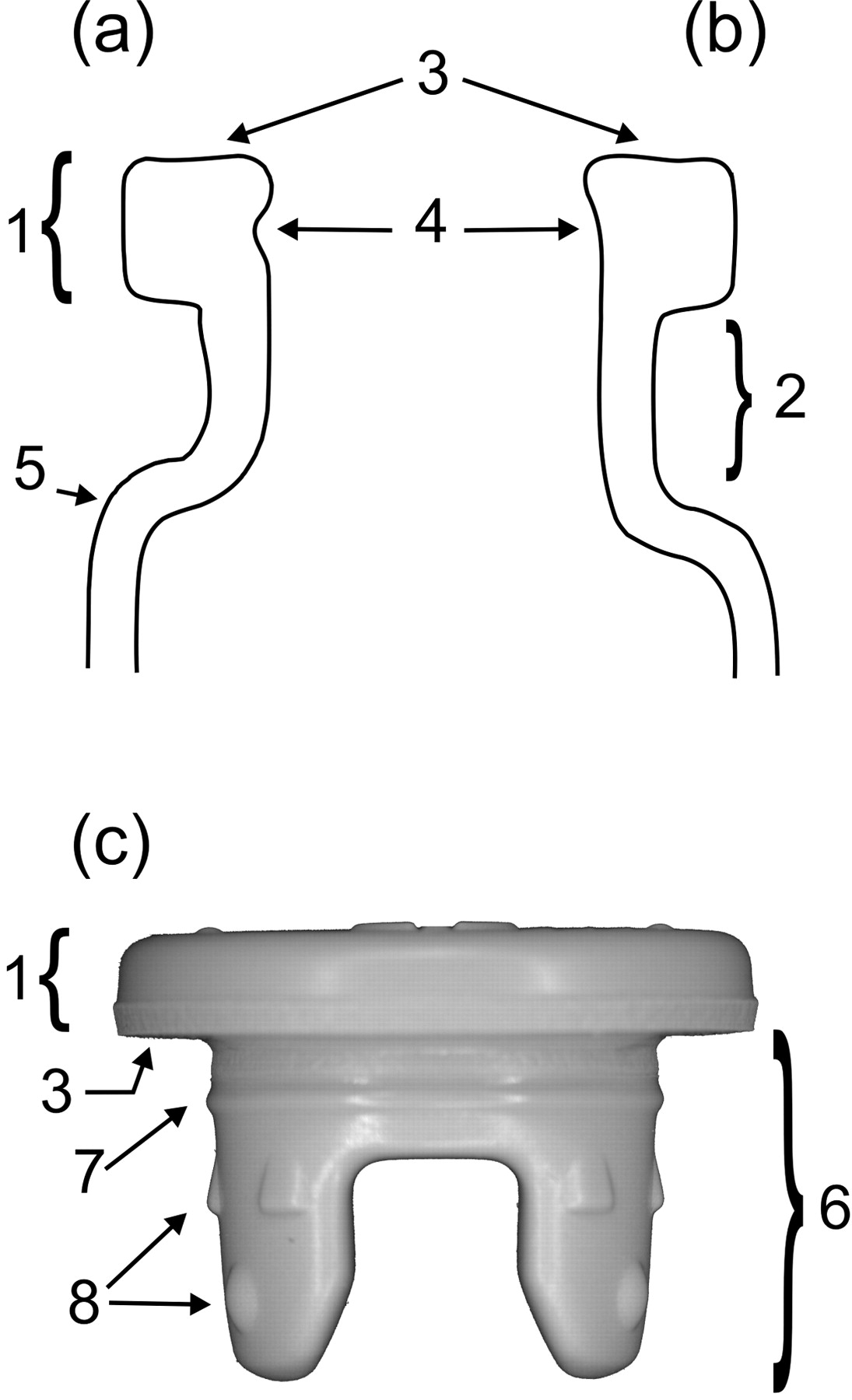
Typical vial profiles, lyophilization stopper and features. (a) American blowback; (b) European blowback; (c) Lyophilization stopper. 1, flange; 2, neck; 3, finish; 4, blowback; 5, shoulder; 6, stopper plug; 7, no-pop ring; 8, vent position nibs.
These concepts are illustrated by the following examples, which were selected to demonstrate the utility of our imaging techniques and to point out insights that can be gained from the analysis of the pictures. The vial and stopper combinations shown are not necessarily ones used in marketed drug products.
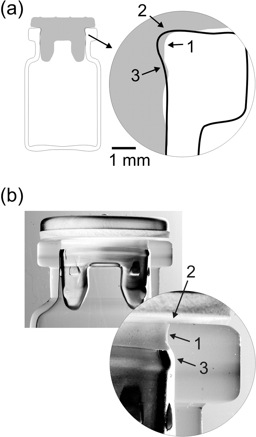
Figure 3 shows superimposed profiles and the corresponding oil immersion photograph of a lyophilization stopper inside a vial with an American blowback. The interference fit at the primary sealing surface (region 1) appears to be adequate for proper sealing. Indeed, the radial compression of the stopper plug over the entire surface circumference is clearly visible in the photograph. At first glance, it would seem that this vial/stopper combination would provide good performance. However, the superimposed profiles also reveal a substantial overlap between the lower part of the stopper plug and the portion of the vial bore below the blowback (region 2). The oil immersion photograph shows how the inward pressure on the stopper legs can deform the stopper flange so that the sealing surface above the vent is raised slightly. In extreme cases (at the limits of tolerances for the dimensions of the components), the deformation can raise the vent high enough to compromise sealing. In addition, this stopper does not have a feature that keeps it fully inserted; occasionally the entire stopper may move up slightly, aggravating the problem. Because the deficiencies are not at the sealing surfaces, manufacturing controls (holding the lyophilization shelves in the collapsed position for an extended period of time, tightly controlling stopper lubrication, and culling when there is a relatively large gap visible between the vial and stopper flanges) can make the performance of this container/closure system acceptable. However, it would be preferable to find a solution that would minimize the deformation at the stopper flange.
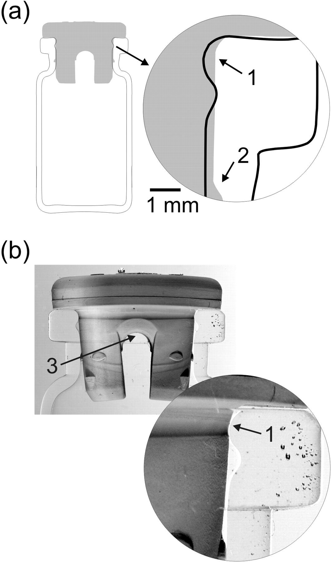
Lyophilization components that have good sealing surfaces, but still fail occasionally because of other less-than-optimal mechanical features. (a) Superimposed profiles of a stopper and vial with an American blowback; (b) Photograph of the assembled vial and stopper. 1, interference fit at the primary sealing surfaces; 2, lyophilization position nib; 3, stopper vent hole.
When we replaced the vial shown in Figure 3 with one that has a European blowback, the overlap between the lower parts of the stopper and the vial bore was nearly eliminated (Figure 4). The extra room for the legs reduced the amount of bowing at the stopper flange, while the good fit at the sealing surface was retained. This configuration is less likely to exhibit vacuum loss issues, but it still could be improved by designing a plug that does not distort the flange when it is compressed and by adding a feature that prevents the stopper from moving out of the vial.
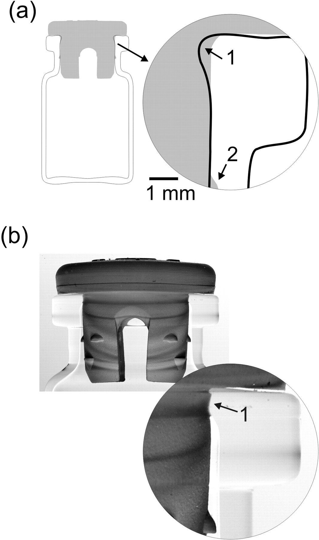
Lyophilization components that have good sealing surfaces but lack a mechanism to keep the stopper fully inserted. (a) Superimposed profiles of a stopper and a vial with a European blowback; (b) Photograph of the assembled vial and stopper. 1, interference fit; 2, lyophilization position nib.
The igloo-style lyophilization stopper shown in Figure 5 has those features. Pressure at the tip of the single leg does not deform the upper part of the stopper even when paired with the American blowback-style vial of Figure 3. The protrusion (a no-pop ring) just below the finish should limit stopper movement when it is in the blowback. However, in this particular case, several deficiencies are evident:
-
The overlap between the stopper and vial at the sealing surfaces (region 1) appears to be insufficient to obtain adequate lateral compression of the rubber. This could result in a weak seal.
-
The shapes of the stopper and vial primary sealing surfaces are not complementary, so the functional size of the sealing surfaces is reduced (region 2).
-
The no-pop ring on the stopper (region 3) is located too low to interact with the upper portion of the blowback when the stopper is fully seated, negating the potential benefit of this feature.

Lyophilization components that frequently loose vacuum. (a) Superimposed profiles of an igloo-style lyophilization stopper and a vial with an American blowback; (b) Photograph of the assembled vial and stopper. 1, interference fit; 2, poor mating region; 3, stopper no-pop feature.
Our prediction that this closure system would not be robust was confirmed when the vacuum was measured by a puncture vacuum gauge immediately after unloading from the lyophilizer: 25% of the packages did not retain a vacuum. Components that appear to be compatible based on specifications and engineering drawings may actually perform poorly.
Figure 6 shows a pairing in which both the vial and the stopper were selected so that the entire package possesses all of the desirable design features. A large primary sealing surface (region 1) is created by complementary shapes and a good interference fit between the stopper and vial. The European blowback (region 3) minimizes bending of the legs, and extra bulk on the plug prevents forces on the legs from being transmitted to the flange. The stopper no-pop ring engages the blowback ridge to keep the stopper fully seated in the vial, and the resulting inward force enlarges the sealing surface slightly (region 2). Extensive testing on our manufacturing lines has confirmed that these components create a primary package that is extremely robust mechanically. Packages that were stored for months without aluminum crimps retained a vacuum and passed dye-leak container/closure integrity testing.
Lyophilization components that have robust sealing surfaces and robust stopper retention features. (a) Superimposed profiles of a stopper and a vial with a European blowback; (b) Photograph of the assembled vial and stopper. 1, interference fit; 2, additional sealing region; 3, stopper no-pop feature.
In the above examples, we presented cases using only 20-mm lyophilization components because they were available and performance could readily be assessed by measuring vacuum retention. However, the techniques can be utilized to visualize other sizes and types of components. The design features that make a robust seal for a 20-mm lyophilization stopper are similar for serum stoppers and other finish sizes.
Conclusions
Many vial–stopper combinations do not make a complete package that seals robustly. The shapes of the vial and stopper sealing surfaces must be complementary for the primary packaging system to function properly. To obtain an optimum primary package, it is not sufficient to just provide a good interference fit; other design aspects, including the overall disposition of the stopper plug in the vial bore, must be considered as well. Features such as the no-pop ring or lyophilization vent position nibs on stoppers can greatly enhance the package's performance but only if they are properly located to mate with corresponding features in the vial. The methods we propose are easily carried out experimentally and can greatly facilitate the assessment of glass and elastomer interactions in the interface area of the vial that is not normally visible. Analysis of profiles and photographs provide insights into the elements that contribute to forming a robust vial seal prior to the application of the aluminum crimp. These techniques, while not statistically rigorous, provide a more systematic approach to component selection and are useful tools for screening vials and stoppers.
- © PDA, Inc. 2010


