
Abstract
A new major chapter dealing with container closure integrity was released by the United States Pharmacopeial Convention. Chapter <1207> provides a significant amount of education and guidance concerning test methodologies to prove that a system is integral and safe for use. The test method used is only one of the major considerations in approaching the challenge of proving an integral system. This paper takes a holistic review of all the major considerations needed in qualifying a new vial system for container closure integrity. There is substantial interplay among many aspects in the process of sealing a vial. This review helps to define major risks that need to be considered and mitigated and reinforces the need to understand the maximum allowable leakage limit that is acceptable for a specific drug application. A typical risk-based approach considers materials, test methods, process, people, environment, and equipment. Each of these aspects is considered in some detail along with a recommended process flow for building a best practice, science-based approach. This approach will inform decision making for evaluating the correct combination of components and assuring they are assembled and tested in an appropriate manner. This work, once completed, can be the basis for a vial system platform or specific drug application qualification.
LAY ABSTRACT: Container closure integrity is a fundamental requirement of every sterile drug package. With recent upgrading of compendia standards and guidance around this issue, there is an opportunity to better define a best practice approach to a complicated subject. It is important to recognize that there is substantial interplay among the components of the system, the process of assembly, and the test methods that are used. This paper takes a holistic approach to discussing these issues and identifying the risks that must be considered in assuring an integral container over the shelf life of a drug product.
- CCI
- Container closure integrity
- Integral system
- Leak rate
- Vial system
- Leakage sealing optimization
- Seal integrity
- Residual seal force
Introduction
The United States Pharmacopeial Convention (USP) released Chapter <1207> Packaging Integrity Evaluation—Sterile Products (1) for implementation August 1, 2016. To raise industry awareness of this chapter, a holistic strategy to assess the container closure integrity (CCI) of a sterile, parenteral container closure system (CCS) is discussed. CCI is proven when a package meets its specific maximum allowable leakage limit (MALL)—the smallest gap or leak rate that puts product quality at risk—established to maintain product quality attributes for sterility and physiochemical stability throughout expiry (1). Many of the examples presented are specific to a stopper/vial/seal CCS format; however, the points reviewed apply to any type of sterile packaging system. This paper can be used as a reference to proactively define a CCI program and any comprehensive corrective and preventative action (CAPA) plan.
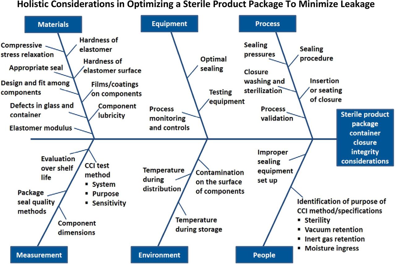
Figure 1 is a comprehensive fishbone diagram defining the numerous aspects to consider when designing a holistic CCI guideline. A popular approach in quality risk management is to apply an Ishikawa analysis and/or failure mode and effects analysis (FMEA) to various aspects of the pharmaceutical development and manufacturing process. An Ishikawa analysis, commonly called a fishbone diagram, is a visualization tool for categorizing the potential sources of a problem. An FMEA is a common, highly structured system technique used by many industries to identify the root causes and effects of various failure modes. This method can help prioritize mitigation plans for the highest potential risks.

Fishbone diagram conveying a comprehensive view of the factors that have an impact on assuring adequate CCI.
This paper will review the following areas:
Materials—important characteristics of the individual packaging components
Equipment—various manufacturing devices used to seal sterile packages
Process—key parameters that can impact package assembly
Measurement—CCI testing methodologies
Environment—factors within the environment in which a package is filled, sealed, or distributed
People—importance of qualified, trained personnel
Each constituent is broken down to establish a fundamental framework that evaluates the risks to consider when selecting and qualifying an integral packaging system. This assessment can subsequently be utilized as part of a formal risk assessment process.
In addition, a process flow for selecting individual packaging components and determining their suitability as an integral system is depicted in Figure 2. Each aspect of the overall framework needs to be gauged together—not independently—to ensure an optimized package.
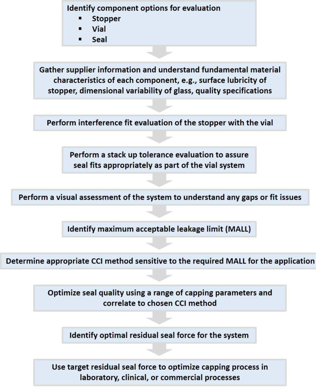
A general process flow that should be applied to qualify the combination of components into a system to assure adequate CCI for a drug application and meet the compendial standards. Consideration should also be given to understanding CCI over the shelf life of the system.
Currently, there is no industry best practice standard defined for qualifying an acceptable CCS platform for CCI. An overarching methodical approach, which focuses on the fitment of the components and how they mate, allows one to demonstrate that a CCS platform is acceptable and then to limit future studies to critical drug product-specific issues.
1. Materials
The most popular CCS used for parenteral drug products is the glass vial configuration. The primary parenteral vial system is composed of three main parts: (1) glass vial container, (2) elastomeric stopper, and (3) the aluminum seal (typically with a plastic button).
These components come together as the primary system that provides the barrier to protect a sterile drug product from product loss and from microbial or environmental contamination.
Individual Component Properties
There are factors for each of the individual components that should be considered to ensure the totality of the system upon assembly. Key elements that can influence the overall package integrity are discussed.
Glass Vial Container
Container Defects:
The composition and properties of the components constituting a packaging system are critical to CCS integrity throughout shelf life. This doesn't solely refer to material characteristics, but the consistency of quality attributes over time.
For example, the ability to have a defect-free container, especially along the land seal in a vial system, is critically important to maintaining CCI. Unless the manufacturing operation incorporates 100% in-line CCI testing, there isn't an assurance that every vial provides integrity. Understanding the fit of the products used within a system and a thorough validation of the overall process is absolutely necessary to mitigate potential risks and achieve integrity. A complete analysis must be performed to account for the dimensional variability encountered from lot to lot, including tolerance intervals, defect levels, and location, and so on. The land seal surface is not the only area of concern for defects. Various defects that can lead to CCI failures are shown in Figure 3.

Examples of quality defects that can affect CCI of a vial system. Defects of either the stopper or the glass vial have the potential to affect integrity.
Elastomeric Stopper
Hardness of Elastomer:
One of the benefits of using a rubber elastomer in injectable closure applications is its ability to flow and form a seal with other materials. This property can be negatively affected if the composition of the elastomer itself or the surface of the component is too hard.
Rubber hardness is typically reported in Shore A units. The term durometer is used to refer to the measurement of hardness and the instrument used to perform the test (2). Durometer is a function of the elastomeric formulation and is assessed using a test plug during the development process. The hardness needs to meet requirements for other aspects of functionality that may be important to the component and the system, yet still fulfill the needs of maintaining CCI.
Based on a historical review (3), an elastomer used for stopper/vial system applications is 45-55 Shore A durometer. This provides the right balance necessary for adequate seal integrity and optimal functionality in terms of coring and reseal after needle punctures. The durometer of rubber may vary from this range depending upon the specific application. For instance, an elastomeric rubber formulation may be designed to be softer if certain films or coatings are intended to be applied to its surface. In other circumstances, such as a plunger in a syringe system, the formulation durometer may be greater to aid in the function of the delivery.
Material Modulus:
Modulus of the elastomer is a critical property to a component and its tendency to deform during assembly. Modulus is a measure of the stiffness of a solid material. It defines the relationship between stress (force per unit area) and strain (proportional deformation) in an elastomer.
Elastomer Viscoelasticity:
The stress decay of polymers under a constant compressive stress is known as compressive stress relaxation (4). This property is an inherent viscoelastic feature of elastomers that may directly affect the ability of a CCS to maintain CCI over an extended duration. Typically, people refer to compression set of rubber; however, compressive stress relaxation is more applicable to CCI for a vial system because it conveys the preservation of a sealing force at a constant deformation (5). There are testing standards for this characteristic: ISO 3384-1 Rubber, Vulcanized or Thermoplastic – Determination of Stress Relaxation in Compression—Part 1: Testing at Constant Temperature and ASTM D6147 Standard Test Method for Vulcanized Rubber and Thermoplastic Elastomer—Determination of Force Decay (Stress Relaxation) in Compression. Research is currently ongoing by Qingyu Zeng, Ph.D. and Cathy Zhao, Ph.D. (6) to characterize stress relaxation over time and understand its implication on residual seal force (RSF). RSF is discussed in greater detail later in this article.
Consequently, the ultimate goal is to optimize the material parameters needed to ensure adequate sealing. There are two types of sealing to consider. The seal for the vial system is static. A static seal signifies minimal motion between the mating surfaces. For a plunger in a syringe system, both a static seal (over shelf life) and a dynamic seal (during break loose and extrusion) are required (7).
Component Surface Lubricity:
An overlooked attribute of many elastomers is lubricity and its relationship to CCI. Component lubricity is an important feature for running in equipment or functioning within a CCS.
Lubricity is the measure of the reduction in friction. A component's total friction is an aggregate of two distinct constituents: (1) sliding friction and (2) lubricated friction (8). Sliding friction occurs when two surfaces are moving over each other. This is influenced by the composition of the interacting materials and the properties of their surfaces. When a layer of liquid lubricant is between two solid surfaces, the friction that exists is called lubricated friction (9). A common lubricant used to reduce friction on component surfaces is polydimethylsiloxane fluid, generally known as silicone oil.
There is a tendency to think that “more is better” and a reduction in surface friction is better for functionality. However, it should be understood that a lubricant applied to a component's surface has to be optimized for its intended purpose. For example, a higher level of lubrication may aid the machinability of a component on the manufacturing line, but it can lead to potential chemical or particulate incompatibilities (10, 11) with the drug product being filled.
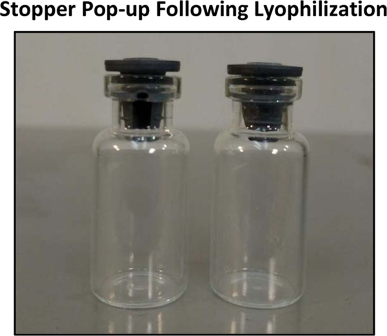
Too much lubricity (or too little friction) can result in performance-related issues for a packaging system that leads to insufficient CCI (12), most notably due to stopper pop-ups. Pop-ups are especially prevalent with lyophilization stoppers due to the presence of a longer plug as depicted in Figure 4. A slight pop-up may be enough to allow a lyophilized product to lose its vacuum or any inert gas within the vial headspace.

Example of stopper pop-up phenomenon that can occur immediately after completion of the lyophilization process but before flip-off seals are used. The stopper pop-up can vary in amount; however, any stopper movement can cause a breach in integrity. Photo courtesy of Ed Trappler and Lyophilization Technology, Inc.
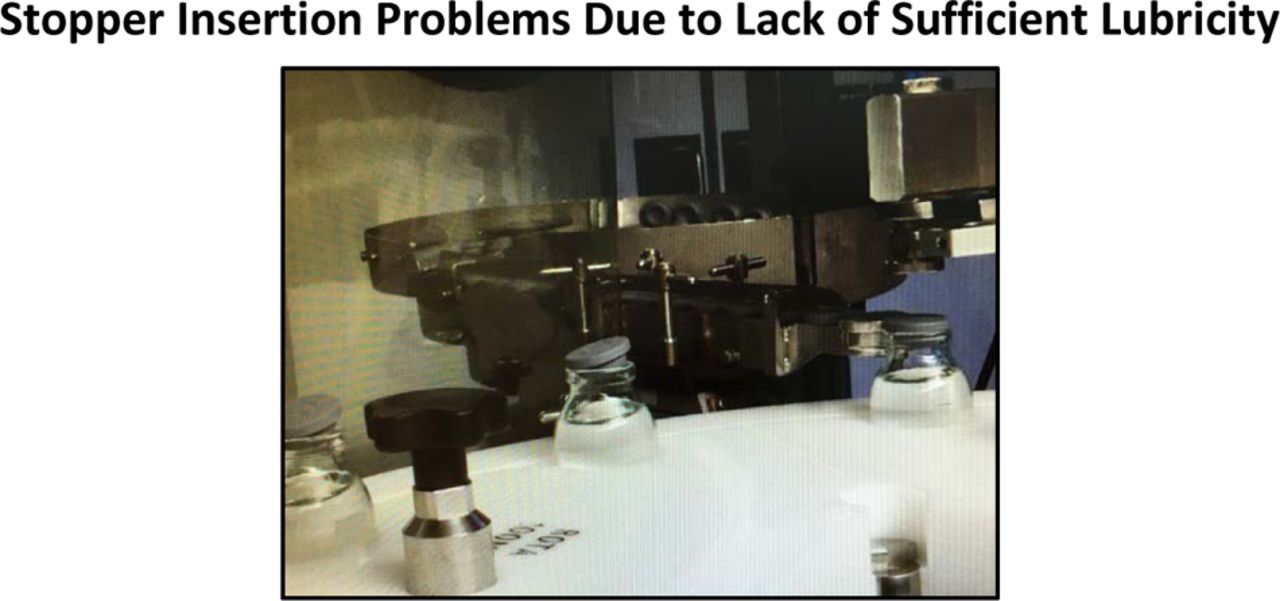
On the other hand, too little lubricity (too much friction) on an elastomeric closure can contribute to machinability obstacles and improper stopper insertion into a vial upon assembly, as shown in Figure 5.

An example of a stopper that does not have enough surface lubrication. This leads to the stopper popping up following insertion into a glass vial. Friction between the interface of the stopper and glass may affect machinability or other issues that indirectly lead to poor integrity. Photo courtesy of West Pharmaceutical Services Scientific Insights Lab, Exton, PA.
Realistically, it is hard to consistently administer an optimal amount of fluid on components to reduce friction. In recent times, striking the correct balance of lubricity for machining and insertion of closures into containers is accomplished with the use of films or coatings. Adding a film or coating provides a more consistent surface.
Films/Coatings for Closures
It is crucial to understand if the elastomeric component uses a film, coating, or a combination of both. The major difference between the two is the method with which they are applied to a surface. Coatings can be sprayed, tumbled, or affixed via vapor deposition, whereas films are typically molded onto components. The purpose of a coating or a film can vary depending upon its intended use. Some are added to components only for increasing lubricity. Others enhance lubricity and also provide barrier properties between the elastomeric matrix of the closure and the drug product being contained (e.g., fluoropolymer films). For the purpose of this review, specific considerations of these coatings and/or films are to be discussed only as they relate to the CCI of a vial system.
Any coating or film will affect the surface hardness/microhardness of the closure—with the exception of silicone oil or polymerized silicone coatings. Silicone oil provides lubricity without altering the nature of the elastomer itself.
Rubber elastomers have been used for many years in sterile applications because of their sealing properties. Such sealability results from the elastomer's viscoelasticity that enables the rubber to “flow” and “seal” (13). This characteristic helps maintain a vial system as integral despite small imperfections in the glass container. When using a closure with a coating and/or film, its applied location must be recognized. Anything that comes in between the closure and container needs to be properly characterized and controlled to mitigate CCI and seal integrity problems.
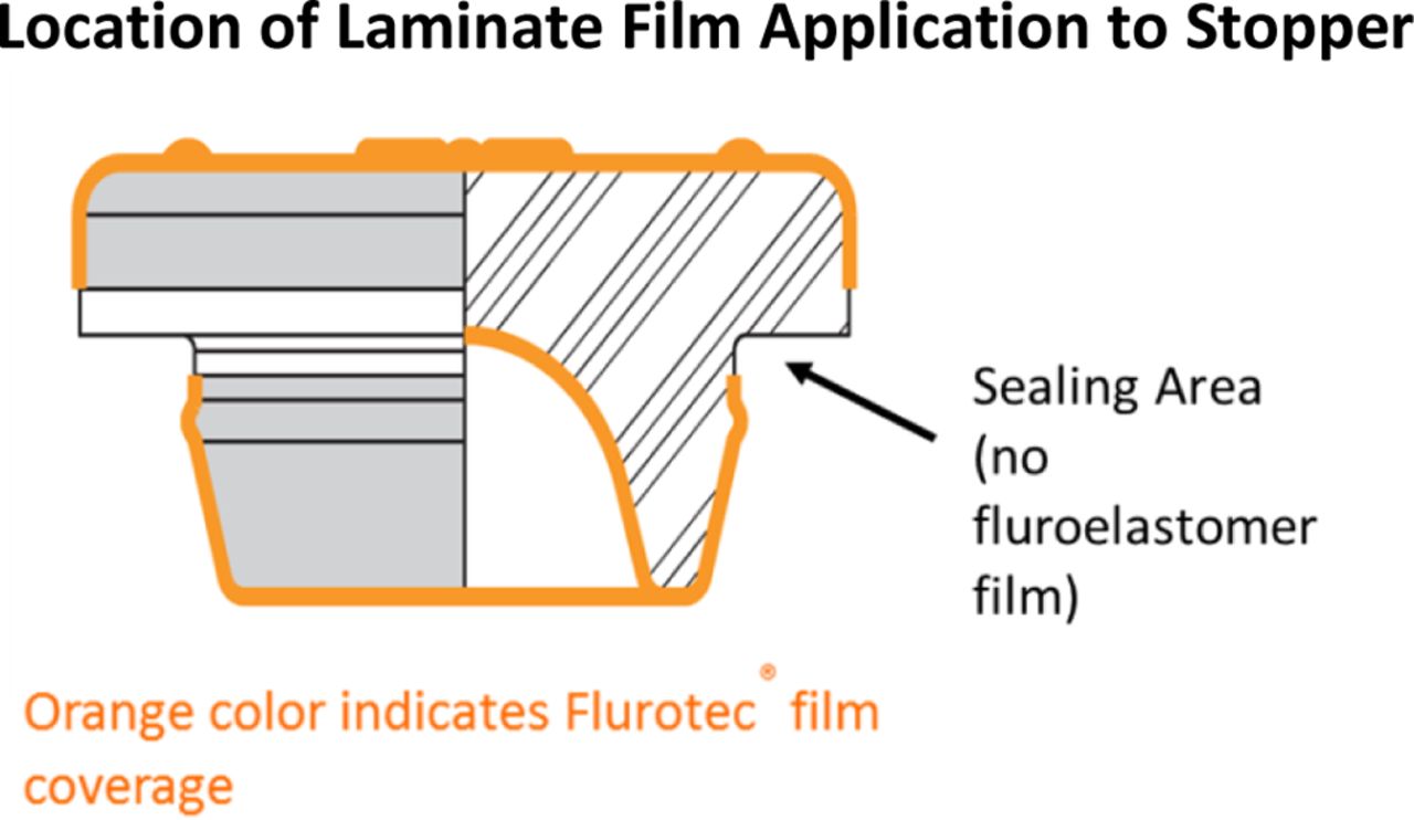
Figure 6 illustrates the location of a film molded onto a typical stopper. The land seal areas of the stopper where sealing occurs do not contain film. Sealing can occur in multiple locations of the assembly, as shown in Figure 7.

Diagram of a laminated stopper that shows the location of the film laminate on an elastomeric closure. The location of a coating or laminate is important in understanding the fit as a system. Photo courtesy of West Pharmaceutical Services, Exton, PA.

Sealing between the stopper and vial typically occurs in three places. The primary seal is between the flange of the stopper and the top surface of the glass, this is the land seal. The other seals are located between the plug of the stopper and the inner surface of the neck of the vial and at the transition between the plug and flange. Image courtesy of West Pharmaceutical Services Scientific Insights Lab, Exton, PA.
In the pharmaceutical packaging industry there has been the development of alternatives other than film coatings that can provide similar benefits. These coatings can be sprayed or applied through plasma or vapor deposition processes using materials such as polyvinylidene fluoride (PVDF). These coatings are typically applied after the elastomer has been molded and trimmed and typically cover the entire closure surface (14).
Coatings on closures have been found to potentially affect the elastic modulus of a closure, especially based on the thickness and rigidity of the coating applied (14).
Fit among the Components/Use of Appropriate Seal
Selection of Container Closure Components To Assure System Fit:
Closure Design:
Elastomeric stoppers are designed for either serum or lyophilization purposes. Historically, stoppers and vials were not built as an integrated unit. The rubber closures recommended and currently used were created independently from the containers.
The configuration or shape of the stopper, including dimensions and the presence of a “no-pop” ring, are important for determining an integral fit of the components. The ensuing evaluations will aid in establishing whether the chosen components are suitable as an assembled system.
Interference Fit:
The first step to assess component suitability as a potential packaging system involves performing interference fit calculations. The fit between the glass vial and the stopper plug is fundamental to the achievement of CCI. This involves evaluating the stopper plug outer diameter with the inner neck diameter of the glass vial. It provides initial information about the amount of rubber in contact with the vial. Too much interference between the stopper and vial could indicate a risk of stopper pop-out, while not enough could lead to a leak in the package. The recommended interference fit is between 3% and 5% (15) and has served as a historic reference point for demonstrating good performance. It can be found to vary from this range and still function successfully as a system. To account for a worst-case scenario, calculations should include the dimensional tolerance intervals of each component to identify the absolute limits of the proposed configuration. Nevertheless, these estimations only serve to approximate the gross fit of the stopper and vial combination.

Stack-up Tolerance:
Maintaining CCI of a packaging system is highly dependent upon the addition of the aluminum overseal to the stopper-vial combination. Most commonly used on parenteral products is the Flip-Off™ seal. The Flip-Off seal is composed of an aluminum ferrule and a plastic button. The button can be removed to access the drug product via a needle puncture through the stopper into the vial. There is typically a target ring at the top of the stopper to indicate the location for needle entry into the stopper. The seal holds the stopper in place and applies force between the stopper flange and the vial at the land seal. The land seal is the primary seal that preserves CCI in a vial system. Figure 7 depicts a typical vial system and the locations of each sealing area. The recently released PDA Technical Report No. 76 “Identification and Classification of Visible Nonconformities in Elastomeric Components and Aluminum Seals for Parenteral Packaging” defines three sealing regions:
Valve seal—formed between the vial neck and the plug of the closure
Transition seal—formed between the top of the closure plug and the vial mouth
Land seal—compression seal formed between the closure flange and the horizontal plane of the vial finish (16)
A stack-up tolerance assessment evaluates the appropriate aluminum skirt length needed for an acceptable crimp upon capping a vial. It is imperative to choose a seal with proper dimensions in order to obtain an integral CCS system. The evaluation of a seal's dimensions relative to a specific stopper-vial combination is calculated as a function of stopper compression.

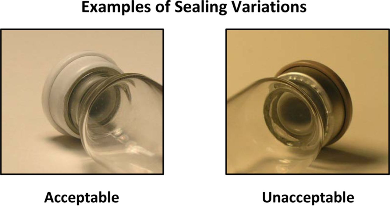
Figure 8 illustrates a vial system with an adequate crimped seal compared to one that is aesthetically unsatisfactory. In general, an excess skirt length of ≥0.76 mm is required for an acceptable crimp. However, there are circumstances where too much excess skirt length can introduce an undesirable “cosmetic” defect underneath the lip of the vial after capping. Excess skirt length can also result in insufficient closure compression that can lead to leakage. It also has the potential to score/damage the neck of the vial, leading to a weakness in the glass which can lead to breakage.

On the left is a picture of an acceptable quality seal, and on the right is an unacceptable seal from a visual quality or cosmetic standpoint. Typically it is a combination of a sealing process that has been validated through the use of an appropriate CCI method and an acceptable cosmetic appearance that qualifies a package for use.
Visual Analysis:
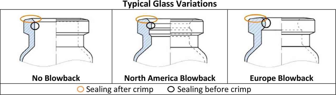
Most glass vials come in three different variations as a function of blowback feature: (1) None, (2) North American, or (3) European. Typically, glass vials used for parenteral drug products contain a blowback. The blowback style for Europe is different than for North American vials, as exhibited in Figure 9.

There are multiple styles of glass vial designs. These show representative styles of vials with no blowback, a North American blowback, and a European blowback. Photos courtesy of Schott AG, Mainz, Germany.
Theoretically, the “no-pop” ring of a stopper is supposed to match with the specific blowback feature of a vial so as to “lock” the stopper in place upon insertion. Because the stopper and glass vials were not designed as systems, either component may not fit properly. A quick indication of improper fit can be observed using various visualization methodologies. Figure 10 reveals the results of multiple stopper and vial combinations (15) visually analyzed via the procedures used in the PDA Journal of Pharmaceutical Science and Technology article, “Visualization Techniques for Assessing Design Factors That Affect Interaction between Pharmaceutical Vials and Stopper” (17).
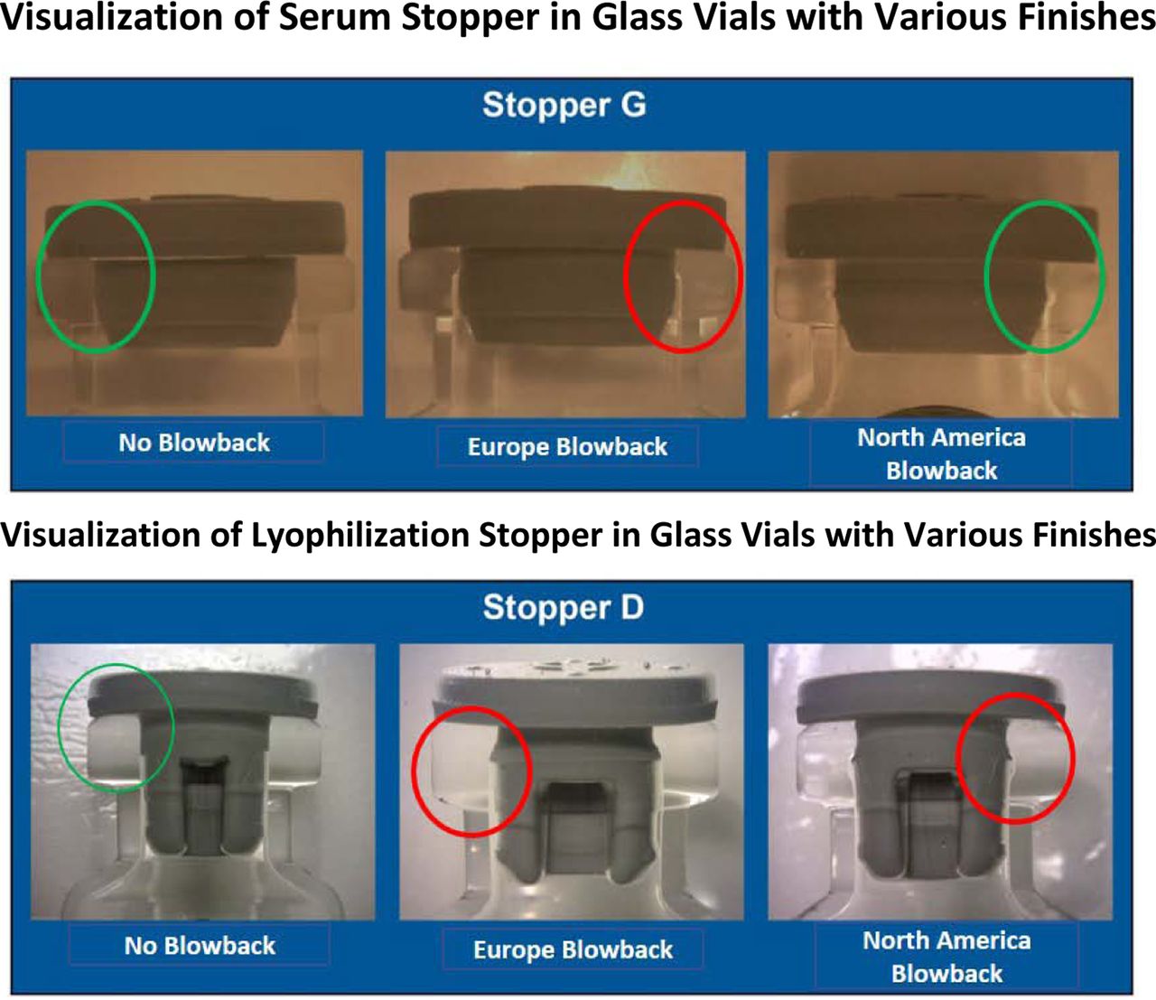
The top photos (serum stoppers) and the bottom photos (lyophilization stoppers) show the results of a visual study to identify the potential mismatch of stoppers to glass design. The designs with questionable fit may not be as robust from a CCI standpoint under a variety of conditions.
2. Equipment
There are several different types of capping equipment for sealing a vial packaging system. These vary in size, sealing technology, and throughput. Basic information about the most common machinery and their mode of operation is discussed.
Lab/Small-Scale Capping Tools
The simplest seal capping tool is a jaw-type crimper frequently employed in a small, bench-scale laboratory. Shown in Figure 11, a jaw-type device usually has four segments that close around the aluminum ferrule of the seal. Increasing applied hand pressure closes the chamber. This concomitantly pulls the bottom edge of the aluminum seal upwards and pushes downwards on the top of the flip-off button (18).

Various jaw type crimping tools have been used historically, especially in the laboratory environment. These are not recommended for sealing vials, especially when there is concern around keeping a system sterile or keeping a system integral in relation to holding a vacuum or inert gas. Photos courtesy of Genesis Packaging Technologies, Exton, PA.
Jaw or hand crimping is not recommended whenever there is concern about upholding CCI. Hand crimping may lead to poor crimping quality that results in sterility or degradation issues (i.e., oxygen/water-sensitive drug products). The jaw crimper equipment and process do not compensate for the dimensional variability of individual components within a system nor does a consistent sealing pressure get applied. This can present inconsistent sealing of the vial capable of sabotaging stability or other related studies.
A second prevalent sealing method is the spinning roller design, as shown in Figure 12. This technique can be used for small or larger volumes of vials. With this instrumentation, a vial is held in position and a spinning roller (or rollers) rotates around the vial. The rollers can be mechanically mounted and found as single or multiple stations. Alternatively, they can be in a fixed position or floating with spring pressure. The shape of the roller edge influences how tightly the aluminum seal is tucked continuously underneath the lip of the glass vial.
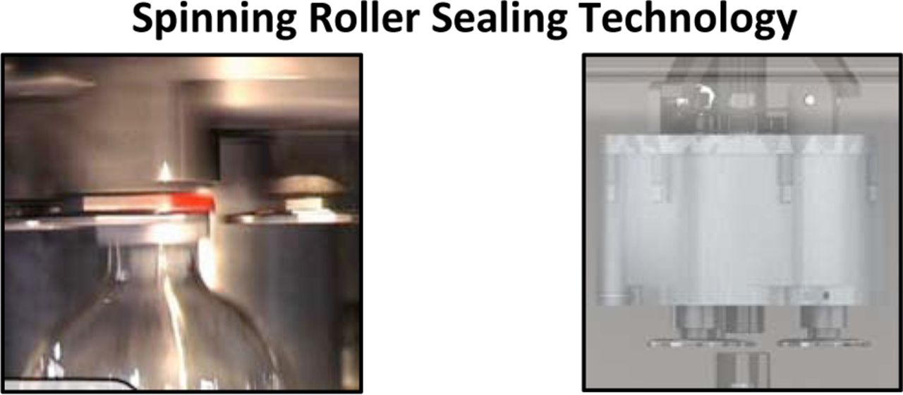
Visual images of the roller as it approaches and tucks the aluminum under the lip of the glass vial. This is an example of a spinning roller sealing process. Photos courtesy of Genesis Packaging Technologies, Exton, PA.
Ensuring the elastomeric closure is pre-compressed to a determined level prior to engaging the rollers is crucial (18). While more complex, a three-spinning roller capper has the benefit of symmetrical positioning of the capping plate around the vial head. The capping process is carried out simultaneously from three directions, resulting in a more uniform and homogeneous folding of the aluminum skirt around the neck and underside of the vial (19).
Commercial Manufacturing Machinery
The third modality of vial capping is a sealing rail where a vial spins against a fixed metal rail seen in Figure 13. This technology is the most common among continuous motion machines. Both the spinning roller and fixed rail technologies are capable of monitoring seal forces throughout the process (18).
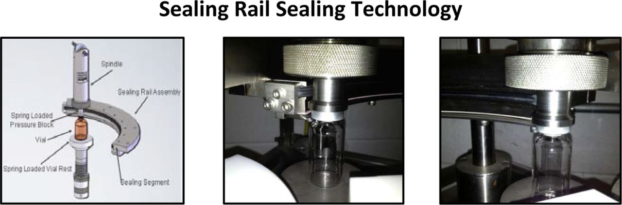
Images of the method by which the vial approaches the fixed rail and spins to fold the aluminum under the lip of the vial. The rail sealing technology is widely used in the pharmaceutical industry. Photos courtesy of Genesis Packaging Technologies, Exton, PA.
The last technique used for large scale manufacturing is a rotary capping plate, and is produced by many equipment manufacturers such as Bausch & Stroebel, Optima, Groninger, and others. Depicted in Figure 14, the rotary capping plate applies a force either above or below the vial for compression. The free-turning rotary plate folds the aluminum skirt underneath the lip of the vial, and can be adjusted in both the horizontal and vertical directions. An additional advantage of a rotary capper compared to others is the generation of lower particulate levels (19).
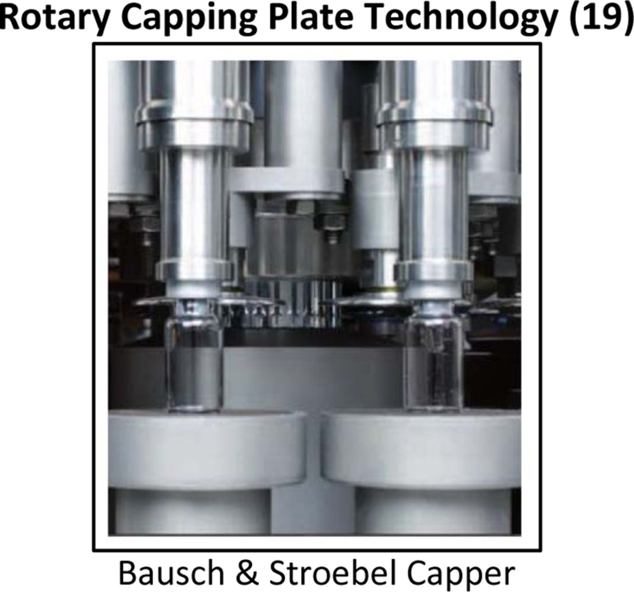
This process of sealing allows optimization of the capping force applied and the crimping of the seal process itself. The benefit with this process is the capability of adjusting both horizontal and vertical directions. Photo Courtesy of Bausch & Stroebel.
3. Process
There is a product lifecycle perspective that needs to be considered during development of a CCI program. CCS qualification should occur with the desired component options or platforms to be employed for a drug's final presentation. It is necessary to look at the vial package in its entirety. This work should begin before first-in-human (FIH) studies, which can subsequently be leveraged for multiple drug products.
Process characterization and validation must be performed to prove CCS integrity as the container is integrated within the manufacturing operation. A package's likelihood of being considered integral may be understood during process development stages. A decision should be made related to the need for CCI and/or seal quality analysis during routine drug manufacturing. Ultimately, CCI must be developed and established for quality control as part of stability and release testing.
The CCS integrity should be considered over the drug product lifecycle. Transportation and storage conditions have to be assessed for each vial packaging system. CCI has to be stable under a multitude of potential circumstances that a vialed product might encounter over its shelf life.
Residual seal force (RSF) is the force that a closure flange exerts against the vial land seal surface of an assembled, capped CCS. The stopper RSF is the first-line indicator to its CCI, and it decays over time and fluctuates with temperature changes due to the viscoelastic nature of the rubber. It is crucial to understand the behavior of the RSF throughout the product shelf life during the manufacturing process development and to establish the optimized ranges of the process conditions to ensure the CCI throughout the drug product shelf life.
Capping Optimization
Optimization of the capping equipment relative to a CCS is an essential next step for achieving a properly sealed vial. There are various equipment parameters that can influence appropriate seal and aesthetic quality. Set-up and operational ranges for those parameters need to be defined.
The vial capping process is a complex interplay of process variables (20) and the specific CCS configuration. The development of a capper setting is based upon reaching sufficient stopper compression using RSF measurements that correlate to definitive CCI testing. Figure 15 displays two relevant capping parameters that can significantly affect resulting RSF values in a rotary plate capper: (1) applied compression force and (2) plate to plunger distance (also called compression zone).

The capping plate to plunger distance shown in this diagram has a major influence on the RSF values of a sealed vial (16). The downward arrow indicates the capping force.
There are two forms of compression that the stopper encounters: (1) pre-compression force occurring prior to capping and (2) the applied force exerted within the compression zone during capping (20). The compression zone can vary based upon the stack-up tolerance of the components. Rubber stopper compression is calculated by determining the ratio of the stopper flange height before and after being capped. All optimization ought to be completed with the exact vial-stopper-seal CCS intended for fill-finish operations.
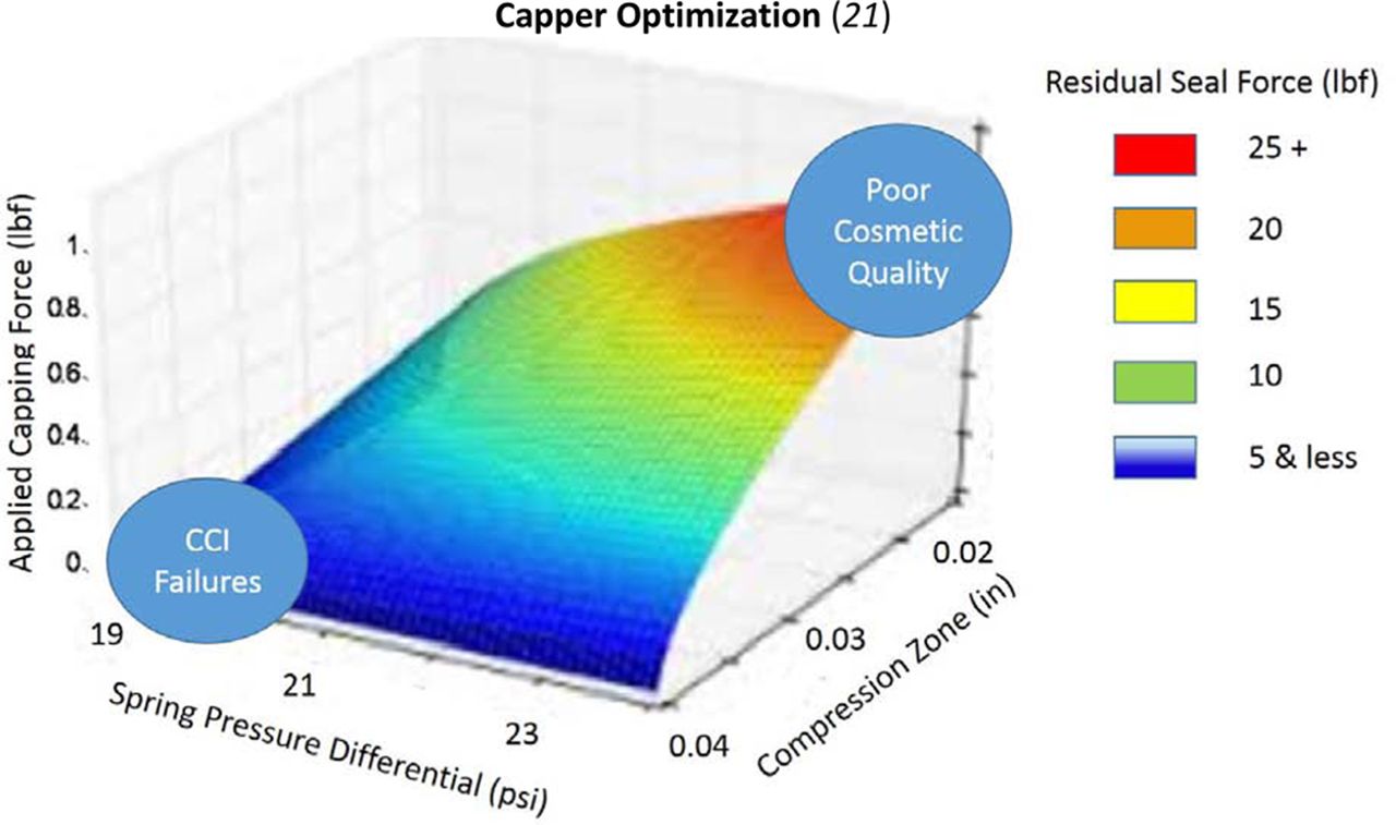
Ideally, the capping process validation would consist of establishing the operational range through a design of experiment (DOE) that evaluates three of the most critical variables of sealing as exhibited in Figure 16 (21):
Compression zone (capping plate to plunger distance)
Stack-up tolerance of components
Direct applied capping force
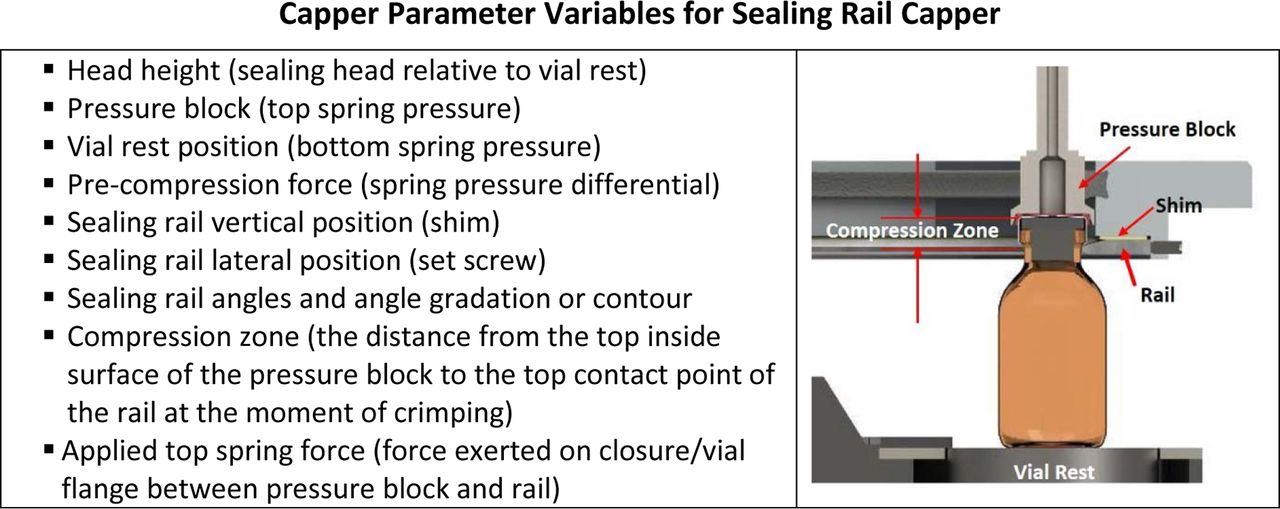
A list of the typical equipment variables found for a sealing rail capper. Each style of capping described will have a set of variables that can be adjusted to assure appropriate sealing. Photo courtesy of Genesis Packaging Technologies, Exton, PA.
The samples that are produced can be tested for RSF to provide an indication of seal quality in combination with a specific CCI test. The CCI test that is used should be based on the maximum allowable leak limit (MALL) determined to be acceptable for the package/drug being sealed. This MALL will vary based on the need to assure sterility and the need to hold a vacuum or inert gas headspace over the product's shelf life. (The technique chosen will also be based on the drug product itself—for instance, high-voltage leak detection is only acceptable for drug solutions that are conductive.) Other critical responses such as cosmetic defects of the seal can also be optimized in this manner.
Figure 17 provides an example of the output that should come from the capping study discussed above. It provides guidance on the conditions that should provide safe sealing conditions. The goal is optimization of processing parameters, not automatically maximizing every parameter. For instance, going to an extreme in direct applied pressure could cause other issues dependent on the closure being used, such as stopper dimpling.

An example of the output of a capping optimization study. A visualization of the resultant data from a DOE as described. In this study the variables used relate to the capping plate to plunger difference, the difference of the pressure of the top and bottom sealing springs and the force applied to seal the vial. This is for design example purposes only.
The results shown in Figure 17 show the interdependence of different process factors. These factors will be unique to every combination of components. An indiscriminate setting of parameters to maximize all factors can lead to other quality implications with the system, therefore a thoughtful DOE process is recommended.
4. Measurement
There are many aspects to be considered in a holistic approach and understanding of CCI, but none more important that an understanding of the CCI test method that is to be used. The fact is that in the pharmaceutical and biopharmaceutical industry there is a need to understand the science behind the decisions that are made. There should be a documented understanding as to why a method is chosen to assure integrity, especially when there is such a direct correlation to patient safety if the incorrect methodology is selected. For instance, if a vacuum is needed to aid in the reconstitution of a lyophilized product, the loss of that vacuum could lead to incomplete reconstitution or extraction of a drug product, therefore delivering an inaccurate dosing of the patient. It all starts with the specific drug application and system. Critical questions are what kind of container format is being used and what is the maximum allowable leak limit that this specific application can tolerate. This limit will vary based on the actual drug packaging system and its specific requirements. Without understanding these few basic questions, there cannot be a truly scientifically sound approach to CCI.
USP Chapter <1207.1> addresses test method selection. The following criteria must be understood:
Package contents
Package design, materials of construction, and mechanics
Closure type and mechanics
Maximum allowable leakage limit (MALL)
Deterministic or probabilistic method
Physicochemical or microbiological methods
Method limit of detection
Leak test detection limit
Leak test method range
Method outcome
Quantitative or qualitative
Non-destructive or destructive
On-line or off-line
In the end, all test methods require optimization for each product package application to ensure a leak test method is able to meet all relevant leak detection performance criteria specific for the test product-package system. Validation of the final methods is also required to demonstrate test method detection and precision and other relevant criteria (22).
Per USP Chapter <1207> section 5 (23), most package types display very low but definite gaseous leak flow through the gaps of even well-fitted closures. Therefore, it is not practical to require that packages be absolutely leak-free. The maximum allowable leakage should be so minimal, however, that it does not affect product safety or the product's physical or chemical stability.
Container products fall into three categories of product-package quality requirements (23):
Sterility and product formulation content must be preserved.
Sterility, product formulation content, and gas headspace content must be preserved.
Sterility must be preserved: product access is required.
These are each detailed to a much greater extent in the USP chapter (23).
Understanding the needs of the individual drug application, coupled with the characteristics of the test methods used, should lead to a more structured and reliable approach.
Figure 18 is taken from a 2014 PDA annual presentation (24). Identifying the MALL for a product-package system is a science- and risk-based decision, per the USP. The CCI method chosen must be able to characterize the correct leakage rate under a given set of packaging conditions.
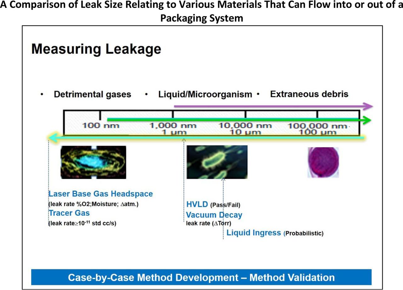
An array of test methods are available for proving CCI. The above chart visualizes the need for more sensitive methods when preventing gas leakage versus methods that may be more appropriate for correlation with microbial ingress.
In USP Chapter <1207.1> section 3.5, deterministic or probabilistic CCI methods are discussed. The chapter defines a deterministic leak test method as one in which the leakage event is based on phenomena that follow a predictable chain of events and leakage is measured using physical chemical technologies that are readily controlled and monitored, yielding quantitative data. Deterministic methods are characterized as being capable of reproducibly detecting leaks at clearly defined and predictable detection limits.
A probabilistic leak test methods is stochastic in nature in that it relies on a series of sequential events—each associated with uncertainties—yielding random outcomes described by probability distributions. Thus the findings are associated with uncertainties that necessitate larger sample sizes and rigorous test conditions controls to obtain meaningful results. Probabilistic methods include bubble emission tests, tracer liquid tests, and tracer gas by sniffer probe methodology. A deterministic leak test method having the ability to detect leaks to the product's MALL is preferred when establishing the inherent integrity of a CCS.
USP Chapter <1207> provides an abundance of guidance and explanation, so it does not make sense to reproduce it in this paper. Anyone interested in the subject of CCI should take the time to read the USP chapter thoroughly.
There are a series of deterministic test methods that one should become familiar with and that are commonly used for evaluating CCI. The following is a list of the typical deterministic methods used by industry:
Vacuum Decay: This technique can be performed on many types of containers with test chambers custom-made to fit securely around each container type. A container with headspace at or near atmospheric pressure is placed in the chamber and vacuum is applied. Then the chamber is isolated from the vacuum source and a pressure transducer monitors change in the chamber. A failure is indicated by a rise in chamber pressure greater than that pre-established by use of negative controls. Each container configuration must be validated separately due to the changes in vacuum settings dependent on chamber size.
Laser-Based Headspace Analysis: This technique is based on frequency modulation spectroscopy. Near-infrared radiation frequency is selected to match an absorbance frequency of the gas molecule of interest contained within the headspace of the container (such as oxygen, carbon dioxide, or water). Radiation passes through the headspace of the container and is absorbed in proportion to the concentration of the gas. Standards of known concentration are used to determine experimental concentrations. Method validation must be performed for each container type, as the data are dependent upon container material/construction and time needed to measure changes based upon container leak rate.
Mass Extraction: This technique (sometimes called mass flow) measures the amount of gas lost from a container. A vacuum is applied to the chamber (often in several stages), and then the chamber is isolated. Absolute pressure, and/or pressure decay rate, and/or gas mass flow rate are measured. Values above a predetermined value established using negative controls indicate container leakage. Method development and validation are required for each new product-package system.
Tracer Gas Leak Detection: This highly sensitive technique measures loss of helium from a container. A helium-filled container (at atmospheric pressure, prepared usually off-line) is placed in a chamber and vacuum is applied. A mass spectrometer measures the amount of helium in the chamber (which is lost from the container) versus time, and a leak rate is calculated. Typically this method is employed with containers void of product to evaluate component compatibility and container assembly parameters.
High-Voltage Leak Detection (HVLD): This technique employs probes to apply a high electrical potential across the entire surface of a container filled with a conductive product. Defects are identified when a discharge is detected by the probes. If a defect is present then the instrument will identify this by recording a drop in the electrical resistance of the test sample. Method development and validation must be performed for each product-package system.
The following is a list of probabilistic leak test technologies:
Bubble Emission: This test is a destructive, qualitative measurement for detecting and locating leaks in nonporous, rigid, or flexible packages containing a headspace gas. It uses internal pressurization. Alternatively, the package can be submerged and exposed to vacuum conditions. Leaks can be observed as a continuous stream of bubbles emitted from the leak site.
Microbial Challenge: This method is a destructive, qualitative method that uses test samples filled with sterile, growth-supporting media, followed by incubation and visual inspection. The samples are then immersed in a concentrated bacterial suspension for a predetermined time. They can be exposed to vacuum conditions while submerged. Samples are incubated and then examined for evidence of visible growth.
Tracer Gas Detection, Sniffer Mode: The sniffer mode test using helium as the tracer gas is described in ASTM F2391, Procedure A. Samples are flooded with the tracer gas. Test samples are scanned with a vacuum wand that is connected to the tracer gas analytical test instrument (e.g., mass spectrometry of helium leak detection).
The sniffer mode testing is probabilistic because the presence of concentrated tracer gas near the sample surface is not well defined or predictable. Additionally, the scanning technique is prone to variability related to human technique. The sniffer mode is typically chosen when a leak location is to be identified.
Tracer Liquid: This destructive approach for detecting leaks in non-porous packages is completed by submersing the samples in a tracer-element solution formulation that is in an evaluation chamber. Test samples are subjected to a vacuum for a predetermined time at a predetermined pressure. After vacuum release, the samples remain submerged for a period of time. Leakage is observed visually based upon the procedure used—looking for egress or ingress of the tracer solution. Visual observation may be supplemented with physicochemical analysis methods such as UV/Vis spectrophotometry to increase sensitivity.
Package Seal Quality Test Methods
In addition to CCI testing, there are methods considered to be seal quality tests. The function of these tests is to properly characterize and monitor seal quality and ensure consistency of package assembly. Quite often, these techniques are used as an indirect way of assuring CCI by building a correlation between an acceptable seal quality parameter and a CCI test. For a stopper/vial system, USP Chapter <1207> cites the use of the residual seal force (RSF) test.
The function of the RSF tester is to evaluate seal tightness by measuring the RSF in the stopper/seal combination created as a result of the sealing process. The RSF is measured by applying strain (compression) at a fixed rate to the seal/stopper/vial package and collecting strain (distance) versus stress (force) data. This data is analyzed by a proprietary data analysis algorithm to determine the RSF (21) in the case of specific equipment such as that supplied by Genesis Packaging Technologies, or it can be generated using universal stress/strain equipment. Work done by Morton and Lordi, published in 1987, showed that an Instron Constant Rate of Strain Testing Machine can provide equivalent results to those generated by a RSF tester. This alternative methodology is described in the published paper (25).
The force applied to deform the stopper creates a reciprocal force from the stopper that pushes upwards. Once the downward applied force is released from the crimped stopper, the reciprocal force created by the deformed elastomer becomes the RSF of the package. RSF is the stress an elastomeric closure will continue to exert against the glass vial finish and the over seal after the capping operation is complete. It is important to understand that RSF is not a constant value. Changes in RSF are the result of stress relaxation and the compression set of the elastomer (21).
The RSF method bears a direct correlation, not only to the vial/stopper/seal assembly, but to how this system comes together with the capping process.
The RSF tester can be used to characterize the resulting RSF of a capped vial independent of the capping equipment used, which can facilitate the comparison of seal quality of drug product units manufactured in different facilities. In addition, a suitable RSF range that would still show full CCI is recommended specific for each CCS combination and can be established using different capping equipment (26).
An example of the correlation of RSF with a CCI method such as helium leak detection can be seen in Figure 19. Each data point is an average of 20 samples that had been sealed at low, normal, and high capping forces. The lower RSF results correlate to higher helium leak detection rates.

A corrleation between a CCI method and RSF can be built. This is then used to optimize the capping process. This graph shows higher leakage values at lower RSFs.

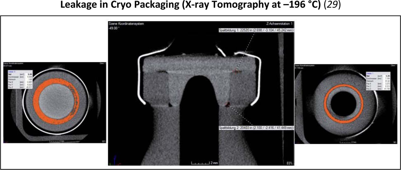
Under extreme environmental conditions, such as cryogenic storage, a physical shrinkage of some of the components can occur. This can be visualized through techniques such as x-ray tomography.
5. Environment
The ability to fill, seal, store, and distribute drug products can occur under numerous conditions that must be considered.
The recommended storage temperatures for drug stability studies are typically at 25 °C and 37–40 °C, although in some instances, higher or lower temperatures may be required (27). Preparations requiring storage at freezing or refrigerated conditions are to be studied at those temperatures (27).
The majority of vaccines require storage and distribution under refrigeration (2 to 8 °C), as exposure to both warmer and colder temperatures may affect their potency. For this reason, maintenance of correct temperature of vaccines is especially critical whether during storage or distribution (28).
Many biologics must be kept frozen, whether at −20 °C or −80 °C, and are typically shipped on dry ice. A more recent challenge is the shipping and distribution of cell-based therapies at cryogenic temperatures (<–150 °C) in liquid nitrogen (28).
Therefore, it is important to understand the CCI of the system through its entire supply chain to evaluate risk. This aspect of CCI, especially under some extreme conditions, must be considered because some materials or packaging systems may not be optimal under certain environmental conditions. These lower temperature conditions, especially below −60 °C, are below the glass transition temperature of a typical rubber stopper formulation. At this point, the stopper loses its viscoelastic properties and becomes glass-like in nature. Under these kind of temperature extremes, materials can shrink or contract thus creating the potential of gaps or leakage to a system.
Considerations during transportation must also be considered because temperatures can fluctuate significantly during air flight or storage under strenuous conditions such as using dry ice during shipping. In the case of more extreme conditions, alternative tools have been used to better understand CCI in addition to the methods referenced in the Measurement section of this paper. An example of this is x-ray tomography. Techniques such as this can supplement typical CCI methodologies to assist with building knowledge about a specific packaging system.
It is important that the package be validated to assure the capability of sustaining the appropriate CCI across its entire shelf life, including a consideration of its thermal history.
6. People
People are involved in choosing, evaluating, processing, and assembly of CCSs. It is important to appreciate the cross-functional aspects of delivering an integral CCS. In addition, engagement with suppliers of both packaging components and equipment used in these processes can highlight potential areas of concern and allow a greater understanding of key high-risk considerations.
In any case, in order to minimize problems and facilitate speed through development, regulatory approval, and manufacturing, appropriate preparatory work is needed.
A benefit of a cross-functional risk assessment approach is that the industry is becoming more familiar with using various standardized tools for risk reduction, such as an Ishikawa diagram or, taking it further, combining it with a failure modes and effects analysis (FMEA).
The International Council on Harmonization (ICH) Q9 document not only contains an explanation of general risk management concepts, but it also contains specific tools for implementing risk management such as FMEA. The benefit of the FMEA over just using the Ishikawa diagram is that it allows for a more detailed analysis of each element of the process that should be considered.
It is recommended that drug formulators, packaging engineers, and other scientists involved in the process of drug development review the various regulatory and compendial standards that discuss the subject of form, fit, and function for drug packaging systems. These standards, coupled with a review reference such as this paper, can be useful tools to assure success in the development of an integral CCS.
The maximum allowable leakage limit (MALL) is the smallest gap or leak rate that puts product quality at risk (1). Based upon the specific CCS and its application, this factor should be defined. This will be based on considerations such as the need to keep out microbes alone or the ability to keep out microbes and retain a vacuum or hold a gaseous headspace over the shelf life of the package. These are some fundamental considerations to be taken for each drug application by the person/team responsible to ensure package integrity.
Considerations to understand sterility and the other requirements for an integral system need to be understood. This is a combination of not only the package, but also its process for assembly.
Conclusion
CCI is a critical aspect of sterile packaging and ultimately to patient safety. A comprehensive approach should be evaluated to assure lowest risk to the patient. This must start during the drug development process and be considered in the technology transfer process during manufacturing and scale-up. By following this concept, knowledge is built that allows a far greater understanding and quantitative assessment of the primary package being chosen for an application. This ultimately delivers a system with a high level of confidence concerning the aspect of CCI.
The recommended approach takes into consideration People, Environment, Methods, Process, Measurement, and Equipment. A thorough understanding of these variables in combination with the recently released USP Chapter <1207> can form a solid foundation to assure an integral sterile package.
Conflict of Interest Declaration
The author declares that she has no competing interests.
Acknowledgements
Roger Asselta, Genesis Packaging Technologies; Ed Trappler, Lyophilization Technology, Inc.; Florence Buscke, Schott; and Doug Duriez, West Pharmaceutical Services, Inc.
- © PDA, Inc. 2018


