
Abstract
As described in USP <1207>, the container closure integrity (CCI) of a pharmaceutical package must be maintained throughout the product lifecycle to ensure sterility and stability. Current CCI test methods can be time-consuming, destructive, and lack the required sensitivity. This study presents a novel, fast, and nondestructive method for CCI testing that uses carbon dioxide as a tracer gas under effusive pressure conditions. Two types of defects were tested: laser-drilled defects located in the glass body (2, 5, and 10 μm nominal diameter) and tungsten wires inserted between the stopper and the landing seal of the vial (41, 64, and 80 μm outer diameter). During each test session, vials were placed in a pressure vessel, isolated from ambient conditions, and pressure-cycled by first pulling a vacuum and then applying an overpressure of pure carbon dioxide gas. After being exposed to 20 psig (34.7 psia) of carbon dioxide for 30 min, the overpressure was released and the vials were measured on an FMS-Carbon Dioxide Headspace Analyzer. This headspace gas analyzer utilizes a tunable diode laser absorption spectroscopy technique that employs frequency modulation to enhance measurement sensitivity. An increase of ≥1 torr in the headspace carbon dioxide content after completion of the pressure cycling procedure was intended to serve as confirmation of leak detection. All empty vials with either a 2 µm laser-drilled defect or 41 µm wire (effective defect size ∼2 µm), or greater, at the stopper-seal interface were detected by this method. Furthermore, vials filled with 1 mg/mL bovine serum albumin in phosphate-buffered saline containing a 5 μm laser-drilled defect below the liquid level or a 64 µm wire (effective defect size ∼6.1 µm), or greater, at the stopper-seal interface (defect above the liquid level) were detected. This test can be used for a wide variety of vial types and headspace compositions.
- Container closure integrity
- USP <1207>
- Headspace gas analysis
- Frequency modulation spectroscopy
- Laser-drilled defects
- Microwires
- Blue dye ingress test
- Microbial ingress test
Introduction
USP<1207> describes a package as having maintained container closure integrity (CCI) if its sealing or closure mechanisms do not risk product quality or safety. This includes prevention of loss of product, prevention of microbial or particulate ingress, and preservation of headspace conditions and composition (i.e., total pressure and purge gases) (1). Up until the revision of USP <1207> in August 2016, microbial ingress and blue dye ingress tests were frequently used for evaluation of CCI (2). Although these tests are accepted by regulatory agencies and can be cost-effective and easy to set up, they also have disadvantages, including being tedious, difficult to perform and reproduce, and can often lead to false negative and/or positive results (3). More importantly, these tests are probabilistic, meaning they rely on a series of events occurring, each event having its own uncertainty, to be successful. This results in random outcomes described by probability distributions. Although there is no “gold standard” for CCI testing, regulators and the industry have now shifted focus toward increasing the implementation of deterministic test methods instead of solely relying on the legacy probabilistic test methods (4). Deterministic test methods are those based on physicochemical technologies and predictable events that generate quantitative data (1). These methods tend to have higher sensitivity and lower detection limits than probabilistic methods and are more straightforward to validate.
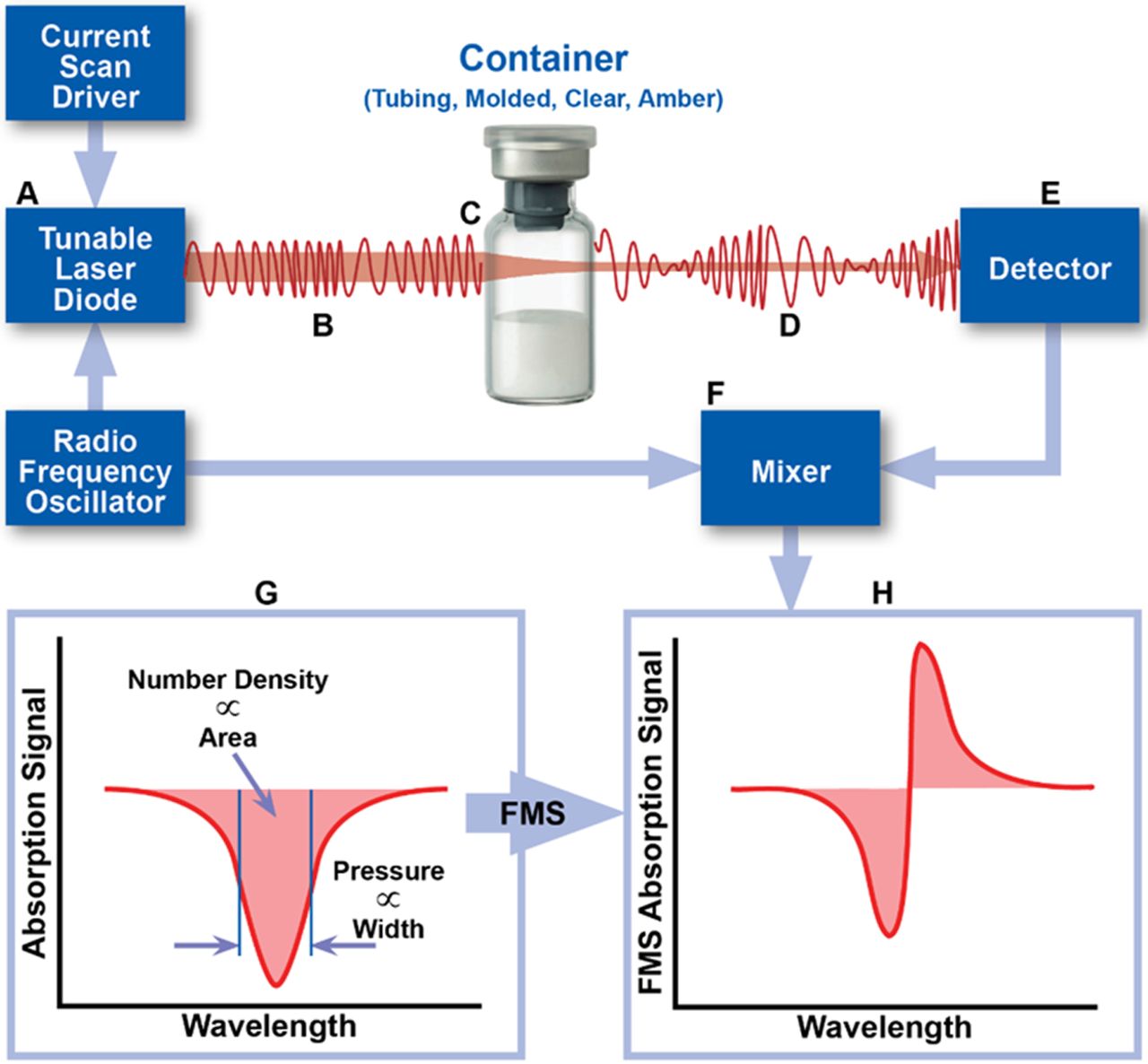
In 2017, Victor et al. demonstrated that laser-based gas headspace analysis, a deterministic leak test method recommended by USP <1207>, can be used to quantify gas ingress into a parenteral package having defects of defined and undefined dimensions (5). This test method is rapid, nondestructive, and can be used on a variety of optically transparent containers. In such applications, the frequency of a near-infrared (NIR) semiconductor laser is modulated and swept through the internal rotational/vibrational frequency of the target gas molecule. Absorption of the light by the target molecule within the headspace changes the amplitude and frequency of the light as it passes through the vial. A photodetector detects this signal, which is subsequently processed by an electrical mixer to generate the frequency-modulated absorption signal associated with the target molecule in the vial headspace (Figure 1). This technique, known as frequency modulation spectroscopy (FMS), increases the detection sensitivity by ∼10,000-fold when compared to the unmodulated absorption signal. The area and width characteristics of the FMS absorption signal provide information about the target molecule number density and/or pressure (6).

Schematic overview of the measurement technique. The area and width of the FMS absorption signal can be used to determine physical parameters of the headspace of a container, including gas number density and total pressure.
Because pharmaceutical products are often packaged under specific headspace conditions, FMS has many applications within the pharmaceutical industry. It was previously used as a method for monitoring the headspace oxygen concentration within sealed glass vials (7), as a method for moisture mapping within a lyophilizer (8), and as a method to detect microbial growth directly in pharmaceutical containers (9). It has also been successfully used as a CCI method for lyophilized products (10) and products stored at −80°C (11).
In order for FMS to be used as a CCI test method, the potential for gas exchange to occur between the vial headspace and its surrounding environment must exist. The lyophilized products studied by Lin et al. (10) and the liquid products stored at −80°C studied by Zuleger et al. (11) both had the additional benefit of the existence of an effusive pressure “driving force”; in other words, any gas exchange, if occurring, would be driven by a pressure differential existing between the headspace of the product sample and its storage environment.
Effusive conditions exist when gas ingress occurs under the force of a total pressure difference. For example, sterile lyophilized pharmaceutical products are often packaged in a partial vacuum under nitrogen. Assuming these vials were stored at ambient conditions (room temperature, air) and a defect was present, air would travel from the high-pressure region (the ambient atmosphere) to a low-pressure region (the vial headspace) until equilibrium was reached. This breach in CCI could then be identified by either the increase in headspace pressure or the presence of oxygen due to air ingress.
The presence of this total pressure difference significantly reduces the time required to detect a leaking vial. Note that in the previous example, total pressure equilibrium is reached first followed by partial pressure equilibrium. Gas exchange that occurs via partial pressure differences (i.e., gas concentrations) is known as diffusion. Without an initial effusive pressure driving force, gas exchange will primarily occur under diffusive conditions, a relatively slow process which, depending on the defect size, can often take days to be observed (5). It should be noted that gas exchange via permeation through the vial components will also occur, but this is not considered a breach in CCI (12).
Therefore, challenges still remain for rapid leak testing of vials that have headspace conditions similar to the atmosphere they are stored in (i.e., air). To decrease the time needed to observe gas exchange for vials packaged at atmospheric pressure, a total pressure difference can be created by subjecting the vials to conditions either below or above atmospheric pressure (13).
CCI tests utilizing the application of a vacuum or an overpressure are not new to the industry. In fact, probabilistic tests, including the previously mentioned blue dye and microbial ingress tests, have variations that include subjecting the system to vacuum and/or pressure after immersion in the appropriate suspension (12). The same is true for deterministic tests including vacuum decay, pressure decay, and helium leak detection. Additionally, helium leak detection, as the name suggests, uses helium as a tracer gas to identify a breach in container closure integrity; the container defect is characterized by a helium leak rate generated by applying a vacuum to the outside of the sample package assembly (1, 2).
This study builds upon the work demonstrated by Victor et al. (5), which established a theoretical basis for predicting the gas ingress through defects in glass vials and verified it with experimental data. The results demonstrated that within minutes, gas flow under effusive conditions can significantly change the headspace composition in vials containing a micron-sized defect. Herein, FMS headspace analysis, coupled with a sample-conditioning pressure vessel, was used to evaluate the feasibility of rapidly detecting defects in vials prepared under ambient atmospheric conditions (∼760 torr of air). With carbon dioxide employed as a tracer gas, changes in the headspace carbon dioxide content were used to identify a breach in CCI by comparing the headspace carbon dioxide levels before and after the sample was subjected to a pressure cycle. This test method is similar to the blue dye ingress test in concept but has the significant advantages of being rapid, nondestructive, and analytical. Additionally, because most pharmaceutical products are packaged with headspaces that contain little to no carbon dioxide, this test has the advantage that even small increases in carbon dioxide could be used as a marker for integrity failure. Laser-drilled defects in the vial glass wall and defects at the stopper-seal interface, created by tungsten microwires, were used to mimic real-world defects. Finally, the effect of product fill and the ability of the method to detect a defect below the liquid level were evaluated.
Materials and Methods
Materials
Laser-Drilled Defects:
Vials (ISO 15 R Schott clear Type 1 tubing glass) were obtained from Adelphi (Part #: VCDIN15R). Stoppers (West Item #: 7002-25,506) and aluminum crimp caps with no flip top were obtained from West Pharmaceutical Services. Laser-drilled defects were fabricated and certified by Lenox Laser (Glen Arm, MD, USA). Defects having nominal diameters of 2, 5, and 10 μm were created approximately 10 mm from the bottom of the vial.
Phosphate-buffered saline (PBS; pH = 7.2) obtained from ThermoFischer Scientific (Gibco) was used to fill all PBS-filled vials. Bovine serum albumin (BSA; CAS #: 9048-46-8, lyophilized powder, ≥96%, agarose gel electrophoresis) was obtained from Sigma-Aldrich. BSA solutions were made in concentrations of 1 mg/mL in PBS. All filled vials contained 5 mL of the respective solution, transferred using a Gilson pipetman, ensuring the laser-drilled defect was covered by the liquid. All samples were prepared under ambient atmospheric conditions, leading to an initial headspace composition of air (∼20.9% oxygen) at a total pressure of 760 torr.
A pneumatic crimper (Kebby Power Crimp, Part #: A10026) was used to crimp all vials using a crimp pressure of 34 psi.
Micron-Sized Wires:
The vials, stoppers, and crimp caps used were the same as those used for the laser-drilled vials. Micron-sized tungsten wires were purchased from California Fine Wire Company (Grover Beach, CA, USA). The wires had outer diameters of approximately 41, 64, and 80 μm. Note that these diameters do not represent the diameters of the defects created by the wires and leak rate measurements were acquired to determine the flow effective diameters of the resulting defects (see Leak Rate Measurements). The filled vials were prepared using the same volumes and solutions as the laser-drilled vials. All vials were stoppered with approximately 1½–2 inches of wire placed between the stopper and the lip of the vial so that one end hung inside the vial and the other end hung outside the vial. For vials that were filled, the part of the wire inside of the vial did not reach the surface of the liquid; however, immediately before the CCI test protocol, the vials were inverted three times to ensure that the liquid came into contact with the defect at the stopper-seal interface. All vials were crimped at 30 psi using the Kebby pneumatic crimper.
Control Vials:
For both the laser-drilled defect sample set and the micron-sized wires sample set, negative and gross positive controls were prepared for testing under the same conditions. The crimp pressure used to fabricate these control vials was again 34 psi for those tested alongside the vials with laser-drilled defects and 30 psi for those tested alongside the vials with micron-sized wires. Negative controls consisted of vials with no defect. Gross positive controls were fabricated by stoppering and crimping an empty vial, pulling back the center of the crimp tab, and inserting a 30-gauge syringe needle through the stopper (inner diameter ∼159 μm).
One-Week Test Vials:
To examine the effect of storage time on the ability of the method to detect a defect, an additional set of vials were filled with 5 mL of 1 mg/mL BSA in PBS and left for one week at ambient conditions before being subjected to the CCI test protocol. Ten each of vials with a 2, 5, and 10 µm laser-drilled defect located below the liquid level and five each of vials with a 41, 64, or 80 µm wire located at the stopper-seal interface were prepared. Vials with a microwire were inverted three times just before the one-week storage period to ensure that the solution came into contact with the defect path. This was done in recognition that in a real-world scenario, the liquid could splash around in the vial (i.e., during shipping or other transport) and temporarily inundate a defect located above the liquid fill level. In this scenario, there could be a higher probability that the product solvent could evaporate through the defect path and leave a precipitate that could obstruct said defect path.
Methods
Leak Rate Measurements:
Leak rate measurements (LRMs) were performed on all laser-drilled vials before and after each CCI test, including an initial measurement session to verify the defect sizes as listed on the calibration certificates provided by Lenox Laser. It should be noted that these laser-drilled vials were reused throughout the analysis and the leak rate measurement performed after completion of the CCI test protocol was used to determine if the defect changed at all during the pressure cycling procedure. To test the flow rate on laser-drilled vials that were filled, the solution was removed, the vials were rinsed with water, left inverted to dry, and then fully dried using a dry nitrogen needle purge.
Initial LRMs on the microwire vials were used to determine the flow effective diameters of the defects. The flow effective diameter resulting from a wire inserted in the stopper-seal interface strongly depends on the vial-stopper combination as well as the crimp pressure used to seal the vials (14⇓–16). Several different crimp pressures were tested in an attempt to create flow effective diameters similar to 2, 5, and 10 μm defects.
Note that when testing the laser-drilled defects on the LRM system, the punctured stopper (which results from attaching it to the system) could be replaced with a new intact stopper after the leak rate analysis and before the subsequent CCI test such that the defect in the vial wall remained unaltered. However, because the microwire defects were created at the stopper-seal interface, removing and replacing the stopper changes the exact leak path. For similar reasons, after completion of the CCI test protocol, only empty microwire vials could be tested for their leak rates. Again, removing the crimp cap and stopper, which would be required to remove the liquid and attach the vial to the LRM system, dislodges the wire and subsequently alters the exact defects created.
All LRMs were acquired using an apparatus designed and assembled by Lighthouse Instruments; it includes a vacuum pump (Thomas, Model #: 2688VE44), a piezo vacuum transducer (MKS Instruments, P/N 902B-42020), and a 23-gauge syringe needle through which the vial is attached to the system. Prior to attaching the vial, an initial atmospheric pressure reading was obtained for approximately 10 s. The sealed vial was then attached to the apparatus by inserting the 23-gauge syringe needle through the stopper. The vacuum pump was turned on and a ball valve used to isolate the sample vial from the vacuum was opened. The vacuum was applied (approximately 5–10 min) until the total pressure inside the vial stabilized between 5 and 8 torr, creating a ∼1 atm pressure differential across the defect. The vial was then isolated from the vacuum by closing the ball valve, and the pressure increase was monitored for a minimum of 5 min. The resulting pressure-versus-time curves were fit using a model developed at Lighthouse Instruments that predicts leak rates of containers of varying headspace volumes, headspace conditions, and defect sizes under effusive flow (5). To briefly summarize, measuring the pressure rise over time allows for an effusion parameter ( ) to be calculated using eq 1:
 (1)where
  represents the total headspace pressure as a function of time,
t,
represents the total headspace pressure as a function of time,
t,  represents the constant, ambient atmospheric pressure,
V represents the headspace volume of the container, and
represents the constant, ambient atmospheric pressure,
V represents the headspace volume of the container, and  represents the effusion parameter of the gas ingressing into the container. The expression in eq 1 is derived from the Hagen-Poiseuille equation for compressible flow and the
  product represents the volumetric flow rate under the conditions in which there is a P0 = 1 atm pressure difference (
 at
at  ) across the container. In other words, the effusion parameter,
  , provides a single (least-squares fit) parameter that fully characterizes the time-dependent effusive gas flow and, when expressed in terms of
  or
or  , can be directly related to the “Air Leakage Rate” as reported in Table I of USP 40 General Chapter <1207.1> Section 3.9. This is because the 1 atm pressure difference matches the conditions at which Lenox Laser, using a standardized flow calibration apparatus, determines the flow effective diameter of their laser-drilled defects. Therefore, by determining the effusion fit parameter associated with the time-dependent pressure rise observed within a container, an effective defect size can be estimated by using the theoretical correlation between the “Orifice Leak Size” and “Air Leakage Rate” reported in Table I of USP 40 General Chapter <1207.1>.
Representative System Performance Data on Flame-Sealed 15 R Clear Tubing Vial Standards. Each Standard Was Measured Five Consecutive Times. The Error Is the Difference Between the Mean and Expected Values. Min and Max Refer to the Minimum and Maximum Values of The Five Consecutive Measurements
The detection limit of the LRM system was determined by measuring negative controls consisting of the same vial-stopper combination with no known defects present. Importantly, these negative controls were fabricated after storing the vial components overnight in desiccant before assembling them. Furthermore, once the negative control was attached to the LRM system, the vacuum was pulled overnight to remove as much of the water as possible. The results acquired with these negative controls demonstrated that the limit of detection of the LRM system was about 8 × 10⁻⁷ standard cubic centimeters per second (sccs), with the caveat that unless the tested sample assembly (vial and stopper) are effectively dried before testing, water desorption will significantly worsen this detection limit by generating a virtual leak.
Headspace Carbon Dioxide Measurements using FMS:
Headspace carbon dioxide measurements were performed using a qualified FMS-Carbon Dioxide Headspace Analyzer, SN 335 (Lighthouse Instruments, Charlottesville, VA, USA). As previously mentioned, the FMS-Carbon Dioxide Headspace Analyzer operates on the principles of FMS employing a diode laser tuned to match a specific transition energy of the carbon dioxide molecule. During a measurement, the laser frequency was repeatedly scanned over the absorption feature and successive scans were averaged to improve the signal-to-noise ratio. The averaged intensity of the FMS absorption signal was proportional to the headspace carbon dioxide number density.
Prior to the measurement session, the instrument was turned on and allowed to warm up for at least 30 min. Calibration was performed with certified flame-sealed carbon dioxide standards containing 0 and 550.2 torr carbon dioxide manufactured by Lighthouse Instruments using National Institute of Standards and Technology (NIST) traceable gas mixtures. The two calibration vials and 10 additional carbon dioxide standards (also fabricated with NIST traceable gas mixtures) at known carbon dioxide partial pressures and total pressures were each measured five consecutive times to verify the performance (i.e., accuracy and precision) of the instrument. This process was repeated for each measurement session. Table I presents a representative set of results and demonstrates that the system calibration and performance for the FMS-Carbon Dioxide Headspace Analyzer were well within specifications, as established by the manufacturer. The linear fit coefficient of the system performance was determined to be >0.999 over the range of carbon dioxide partial pressures 0–550 torr. Based upon the absolute value of the measurement error (the difference between the known NIST certified gas composition and the measured value for each standard) and the measurement precision (the standard deviation of multiple measurements for each standard), the headspace carbon dioxide total measurement error was established as ±1 torr for the range between 0 and 15 torr and ±2 torr for the range between 15 and 29 torr. For partial pressures between 29 and 550 torr, the headspace carbon dioxide total measurement error was established as 6% of the measured value for the 15 R vial format used in this study.
For the analysis of the sample sets presented, the carbon dioxide content was measured five consecutive times during each measurement session.
CCI Test Protocol:
Prior to pressure cycling, baseline headspace carbon dioxide measurements (T0) for each vial were taken to confirm atmospheric conditions (≤1 torr carbon dioxide). Vials were then placed in a pressure cycling vessel built by Lighthouse Instruments and fitted with a pressure relief valve of 40 psi. The vessel was then isolated from the atmosphere and connected to a vacuum (Thomas, Model #: 2688VE44) and a carbon dioxide tank (Roberts Oxygen, Industrial Grade, 99.8% purity). The vacuum pump was then turned on and the valve connected to the vacuum was opened. The chamber was evacuated to ∼100 torr total pressure and was held in this environment for 60 s. After 60 s, the valve to the carbon dioxide tank was opened and the total pressure was brought back up to atmospheric pressure (∼760 torr), at which point the valve to the carbon dioxide tank was closed. The vessel was held in this environment for 60 s. The valve to the carbon dioxide tank was then opened again and the total pressure of the vessel was brought up to ∼34.7 psia (20 psig). The vials were held in this environment for 30 min. After 30 min, the overpressure was released, the vessel was opened to ambient conditions, and each vial was immediately measured five consecutive times on the FMS-Carbon Dioxide Headspace Analyzer (T1).
Results/Discussion
The primary objectives of this analysis were to (1) demonstrate the use of carbon dioxide as a tracer gas for rapid container closure integrity test methods under effusive conditions, (2) determine the effective sizes and types of defects that can be detected using this method, and (3) evaluate the effect of the fill on the ability of this method to detect a defect. Real-world defects were simulated using both laser-drilled vials and vials with microwires at the stopper-seal interface. Additionally, three different fill types—including none (empty), buffer solution (PBS), and a protein solution of 1 mg/mL BSA in PBS—were tested for each size and type of defect. The sample sets are summarized in Table II.
Sample Set Summary. All Samples Were Prepared with ∼760 Torr of Air in the Headspace
Laser-Drilled Vials
Laser-drilled defects having nominal diameters of 2, 5, and 10 μm were examined. LRMs were taken before use in CCI testing to verify the diameters as listed on the calibration certificates provided by Lenox Laser (Table III). After acquiring one LRM on each vial and correlating it to a flow effective diameter (see Materials and Methods), it was determined that, on average, the diameters calculated using the Lighthouse LRM system were within 0.3 μm of those listed on the Lenox Laser calibration certificates.
Flow Effective Diameters Reported by Lenox Laser as Compared to Those Acquired on the Lighthouse LRM System. Lighthouse Values Show the Averages of One Measurement on 10 Vials for Each Nominal Diameter Size
After verifying the diameters of the laser-drilled vials, empty samples were prepared as described in the Materials and Methods. Ten samples of each defect size, as well as negative and gross positive controls, were measured on the FMS-Carbon Dioxide Headspace Analyzer to confirm a baseline headspace carbon dioxide content (T0) consistent with atmospheric conditions (≤1 torr). All vials were then subjected to the conditioning cycle as described in the CCI test protocol and immediately measured (T1). This procedure, including verifying the flow effective diameters of the vials, was repeated for both vials filled with PBS and vials filled with 1 mg/mL BSA in PBS. A summary of the results is presented in Table IV.
Headspace Carbon Dioxide Partial Pressure in Sample Vials with Laser-Drilled Defects, Both Before (T0) and After (T1) conducting the CCI Test within ∼24 h of Sample Preparation. Values Show the Averages of Five Consecutive Measurements on Each Vial. All Vials with a Liquid Fill Had the Defect Located Below the liquid Level
The leak detection criterion for this CCI test method was determined by (1) evaluating the change in headspace carbon dioxide observed in the negative controls and (2) quantifying the standard deviation of a flame-sealed standard containing a trace amount of carbon dioxide, LH-15R-2K (Table I) (17). The results across multiple experimental setups demonstrated that the negative controls had, on average, roughly 1 torr of headspace carbon dioxide; this was confirmed by external monitors that indicated that the laboratory carbon dioxide level was about 1000 ppm. The measurement precision associated with the flame-sealed standards with headspace carbon dioxide contents <10 torr was determined to be ∼0.1 torr. Taken together, the criterion for identifying a breach in CCI was thus established to be 1 torr, meaning any vial with a change ≥1 torr between the T0 (before the CCI test protocol) and T1 (immediately after the CCI test protocol) time points was considered to have a defect present.
All empty vials with each laser-drilled defect size were detected (Table IV). As expected, the sample set containing the 2 μm defects contained the least amount of carbon dioxide at the T1 timepoint whereas the 5 and 10 μm defects had comparable amounts of carbon dioxide. The negative controls had no change in carbon dioxide content and the gross positive controls had a dramatic increase in carbon dioxide content, confirming both the carbon dioxide enriched environment in the pressure vessel and that the method was capable of identifying such defects.
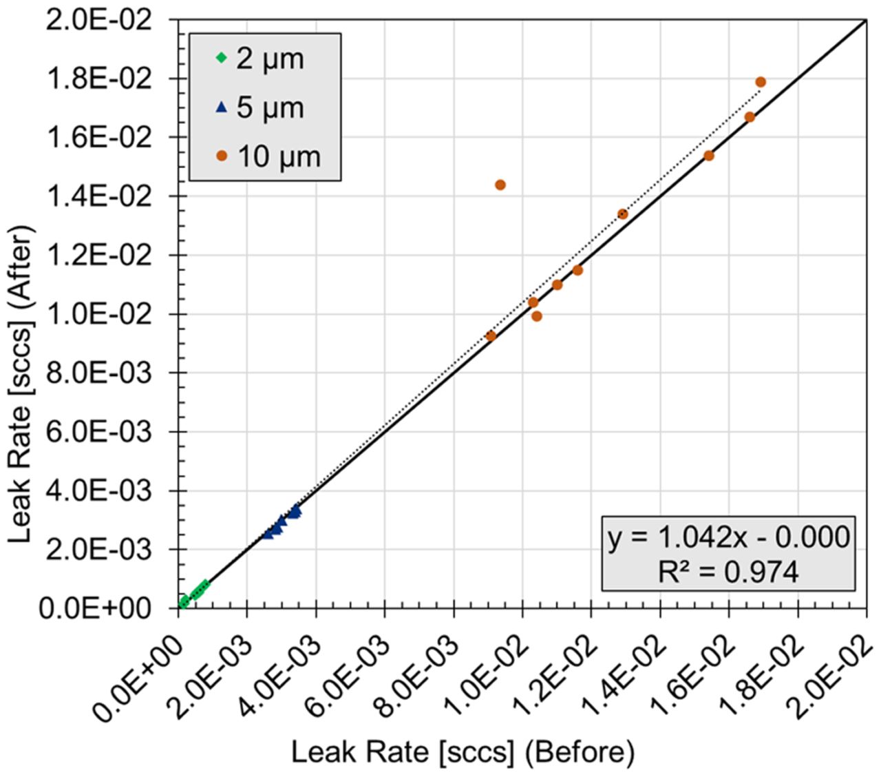
To determine if the CCI test protocol affected the defects, a regression analysis was performed. The leak rates measured before the test were plotted against the leak rates measured after the test (Figure 2). A vial was deemed as having a significant change in its leak rate if the absolute value of the normalized residual was >2. Of the thirty vials tested, one vial with a nominal 10 μm defect did have a significant increase in its leak rate, from 3.35 × 10⁻³ sccs before the test (8.1 μm flow effective diameter) to 1.44 × 10⁻² sccs after the test (10.0 μm flow effective diameter). This was not completely unexpected because the laser-drilled defects are known to have a complex geometry with glass fragments that may shift when subjected to changes in pressure. Because the final leak rate of this vial was still comparable to that of a 10 μm defect, it was not removed from the analysis.

Leak rate measurements on empty laser-drilled vials before and after completion of the CCI Test. Values represent one measurement on each vial.
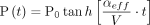
It should be noted that the laser-drilled defects were intentionally placed toward the bottoms of the vials, approximately 10 mm from the base, so that when filled they would be completely submerged in the liquid. This means that during the CCI test protocol, before carbon dioxide could reach the headspace of the filled vials via the effusive pressure gradient, it must first overcome the surface tension associated with the liquid surface at the defect. During this process, the liquid surface will begin to deform into a bubble. The pressure difference that develops at the boundary between the gas-liquid interface and that is required to overcome the surface tension is known as the Laplace pressure and can be described by the following equation:
 (2)where ΔP represents the pressure difference across the gas-liquid interface, γST represents the surface tension associated with the liquid, and rbubble represents the principle radius of curvature. For example, for water at 25 °C where γST = 72 mN/m, the pressure required to create a 5 μm diameter bubble is roughly 432 torr. If a water-filled vial having an idealized circular defect below the liquid was subjected to the CCI test protocol used here, after overcoming the surface tension, 602 torr of carbon dioxide (1034 torr overpressure − 432 torr Laplace pressure) would remain available to pass through the liquid interface and into the vial headspace.
Note that in this example, 432 torr is the minimum pressure difference required for an idealized circular opening; for noncircular shapes, like the defects used in this study, the surface curvature would be greater and therefore would require a larger pressure difference. Because the laser-drilled defects were imperfect, and the surface tensions of the liquids used to fill the vials was unknown, it was difficult to predict the expected headspace conditions of the filled vials; however, the theoretical values displayed in Table V were used to give a general idea of the required pressure under ideal circumstances.
Laplace Pressure Required for Ideal Circular Defects In Water-Filled Vials. The Expected Carbon Dioxide Partial Pressure Is Based on a 20 psi (1034 torr) Overpressure
In principle, carbon dioxide gas ingress could also occur via diffusion through the liquid fill at the liquid interface in the defect path, with no bubble formation occurring. However, the diffusion coefficient of carbon dioxide gas in water (∼1.67 × 10⁻⁵ cm2/s) is roughly 10,000-fold smaller than for carbon dioxide gas in air which, in turn, is orders of magnitude slower than the rate of ingress via effusive bubble formation. Therefore, changes to the headspace carbon dioxide content via diffusion of carbon dioxide gas through the liquid fill were insignificant in the time scale of this method protocol.
Not unexpectedly, none of the 2 μm defects were detected with either the PBS fill or the 1 mg/mL BSA in PBS fill. Referring to Table V, the theoretical Laplace pressure required for 2 μm defects was 1080 torr, and the overpressure used for these cycles was 20 psi or ∼1034 torr. Therefore, even under ideal conditions, the experimental overpressure applied would not be enough for carbon dioxide to overcome the surface tension and ingress into the vial headspace. Furthermore, because the defects used in this analysis were nonideal, the Laplace pressure required was likely even greater. Finally, the defects were only nominally 2 μm. Based on the measured leak rates, their flow effective diameters ranged between 1.0 and 2.4 μm. The theoretical Laplace pressure increases dramatically as the defect size decreases, with a 1.0 μm defect requiring >2000 torr of overpressure just to overcome the surface tension.
Referring again to Table IV, all 5 μm defects were successfully detected when filled with either PBS or 1 mg/mL BSA in PBS. There was a clear decrease in the amount of carbon dioxide detected between the empty, PBS, and 1 mg/mL BSA in PBS filled vials, with the empty vials containing the most carbon dioxide and the 1 mg/mL BSA in PBS filled vials containing the least. This may reflect differences in the surface tension associated with these solutions and/or differences in their dissolved carbon dioxide content, described by Henry’s Law.
The 10 μm defects were also successfully detected when filled with either PBS or 1 mg/mL BSA in PBS. Unlike the 5 μm defects, there was no correlation between the amount of carbon dioxide in the headspace and the fill type. The PBS-filled vials had the most carbon dioxide ingress, followed by the BSA in PBS-filled vials, and then the empty vials. It should be noted, however, that the empty vials had the smallest standard deviation, 21.1 torr, whereas both sets of filled vials had standard deviations >100 torr. This increase in the standard deviation across the samples in these two liquid-filled sets was most likely a reflection of the additional complexities involved with the surface tension at the liquid interface of the defects.
To summarize, the CCI test protocol used here was able to successfully detect 100% of positive controls containing an effective defect size of ≥2 μm when empty, and 100% of positive controls containing an effective defect size of ≥5 μm when filled with 5 mL of either PBS or 1 mg/mL BSA in PBS (defect below the liquid level).
Microwires
Micron-sized wires made of tungsten having outer diameters of 41, 64, and 80 μm were used to simulate leaks present at the stopper-seal interface. These artificial leaks were meant to represent fibers, particles, or other foreign matter that may become trapped in the sealing interface during the stoppering and crimping process. Defects at the stopper-seal interface are arguably more likely to go unnoticed during visual inspection processes, as compared to glass body defects, because they can easily be hidden by the crimp cap. One of the challenges of creating these artificial leaks was that the defect size created by the wire does not directly correspond to the outer diameter of the wire. Additionally, the leak path created was heavily dependent on the components and crimp pressure used to seal the vial. This meant that the defects could vary between different vial configurations, even if the same wire was used.
It should also be noted that the defects created by the wire were essentially two paths, one on either side of the wire. Although these defects will be discussed in terms of both their flow effective size and their leak rate, it is important to remember that it was not a single defect path.
Micron-sized wires have been used in the past to simulate defects at the stopper-seal interface. Nieto et al. demonstrated that uncoated copper wires inserted between the glass vial opening and the rubber stopper can be used to mimic particles or fibers occurring in the sealing area (15). The experiments presented here were based on the same concept, but instead of copper wires, tungsten wires were used. Copper has a high risk of oxidation and is also significantly softer than tungsten. Both of these factors create a higher risk of changes to the outer diameter of the wire, which subsequently may cause increased variability in the defect geometric characteristics during fabrication.
Because the size of the defect is dependent upon the crimp pressure, two different pressures, 30 and 34 psi, were initially tested to determine the optimal configuration. The goal was to create microwire defects having leak rates comparable to the 2, 5, and 10 μm laser-drilled defects while also maintaining an acceptable crimp appearance (i.e., the crimp cap should be tight enough that it cannot be rotated by hand, but loose enough that there are no indentations). To determine the leak rates/flow effective diameters created by the tungsten wires at both crimp pressures, measurements were taken on the leak rate apparatus as described in Materials and Methods. It was determined that 30 psi was favorable, as the crimp caps were not loose or deformed, and the observed flow rates were on the same order of magnitude as those of the laser-drilled defects.
Table VI displays the flow effective diameters and flow rates for vials containing each wire size after being crimp-sealed at 30 psi. Note this data was acquired throughout the study and represents measurements taken after completion of the CCI tests. As previously mentioned, this was because it is currently not possible to acquire leak rate measurements on a sample vial in a way that does not either introduce a syringe puncture to the stopper or alter the leak path. To test the leak rates on filled vials after the CCI test, they would first need to be emptied, which again requires removal of the stopper. On average, the observed leak rates for the defects created by the 41, 64, and 80 μm wires corresponded to flow effective diameters of 2.0, 6.1, and 8.5 μm, respectively.
Average Flow Effective Diameter and Flow Rate for Microwire Defects Created at the Stopper-Seal Interface Using a Crimp Pressure of 30 psi. The Statistics Are Based Upon 29, 30, and 27 Different Samples Fabricated With the 41, 64, and 80 μm Wires, Respectively. Data for the Negative Controls (NC, no defect) are Based on 33 Samples
After determining the optimal crimp pressure of 30 psi, a full set of samples was fabricated for each of the three microwire sizes, including empty, PBS-filled, and 1 mg/mL BSA in PBS -filled versions. These samples, as well as the empty negative and gross positive controls, were tested using the same protocol that was used for their laser-drilled counterparts as detailed in the CCI test protocol (Materials and Methods). Again, a change >1 torr of carbon dioxide after completion of the protocol was considered to be a positive indication of a leak.
Table VII includes the results obtained for the empty versions of this sample set. As expected, the negative controls did not have any observable carbon dioxide increase, whereas the gross positive controls had a substantial increase in carbon dioxide. Compared to those for the laser-drilled defects, the results for the empty microwire samples were less consistent. For example, one sample that contained an 80-micron wire was observed to have headspace carbon dioxide ingress of <1 torr, whereas another sample containing a 41-micron wire had an increase of only 2 torr. All remaining empty vials with wires at the stopper-seal interface showed variable change in headspace carbon dioxide, with the average change increasing with increasing wire size.
Headspace Carbon Dioxide Partial Pressure in Sample Vials with Microwires at the Stopper-Seal Interface, Both Before (T0) and After (T1) Conducting the Container Closure Integrity (CCI) Test within ∼24 h of Sample Preparation. Values Show the Averages of Five Consecutive Measurements on Each Vial. All Vials with a Liquid Fill Had the Defect in Contact with the Liquid Just Before the CCI Test Was Performed
In order to investigate the cause of the limited carbon dioxide ingress in the two empty samples described previously (80-micron wire and 41-micron wire), leak rate measurements were taken on all empty vials with the microwires inserted at the stopper-seal interface. Interestingly, both of these samples had leak rates ∼10−5 sccs, similar to that observed for the negative controls (Table VI). This orthogonal technique confirmed that the defect paths in these samples blocked gas flow. It is unclear how this happened as a visual inspection confirmed that the wires were present on both the inside and outside of the vial. One possibility is that the wire broke in two during the stoppering/crimping process, creating a discontinuous defect that did not form a leak path directly into the vial.
Not surprisingly, the liquid-filled versions of these samples also exhibited a few inconsistencies (Table VII). Note that all liquid-filled samples were intentionally inverted three times just before the CCI test protocol to ensure that the solution came into contact with the defect at the stopper seal. Similar to the results observed for the 2 µm laser-drilled defects (Table IV), the defects associated with the 41 µm wire (∼2 µm effective defect size) were not identified in general; only one out of the 10 total samples was identified (PBS-filled). Conversely, all of the defects associated with both the 64 and 80 µm wire (∼6 and ∼9 µm effective defect size, respectfully) were readily identified (i.e., a >200 torr increase), with the exception of one PBS-filled 64 µm sample, for which the headspace carbon dioxide content increased by only 3 torr. Because these samples were liquid-filled, leak rate measurements were not possible, thus blockage of the defect could not be confirmed.
One-Week Storage Test
All of the results discussed thus far involved sample vials that were fabricated and tested for their CCI within 24 h of preparation. An additional set of vials (laser-drilled and microwire) were filled with 5 mL of 1 mg/mL BSA in PBS and left for 1 week at ambient conditions before being subjected to the CCI test protocol. The intent of this test was to examine the effect of storage time on the ability of the method to detect a defect.
The results for the laser-drilled defects sample set are presented in Table VIII; after the 1 week wait period, none of the ten 2 μm defects were detected (as expected), seven of the ten 5 μm defects were detected, and all ten of the 10 μm defects were detected.
Headspace Carbon Dioxide Partial Pressure in Sample Vials with Laser-Drilled Defects, Both Before (T0) and After (T1) a Container Closure Integrity (CCI) Test that was Conducted 1 Week After Sample Preparation. Values Are the Averages of Five Consecutive Measurements on Each Vial
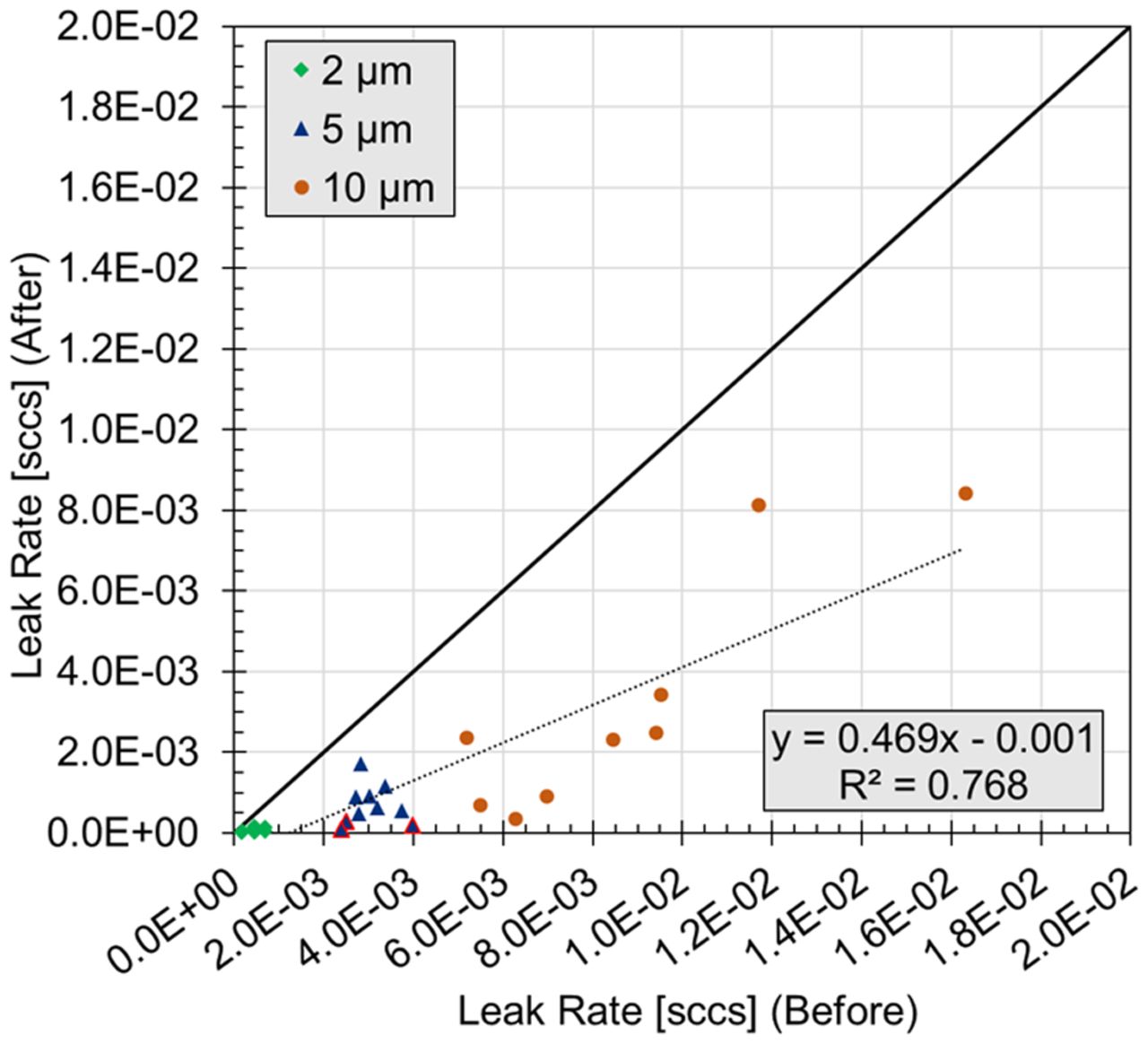
To further understand why a change in the headspace carbon dioxide was not observed for some samples, especially those with a 5 µm defect, the effective defect diameters were once again measured (Figure 3). These results showed that the effective diameter had decreased by an average of 1.0, 2.5, and 3.2 μm for the 2, 5, and 10 μm defects, respectively. The three failures observed within the 5 μm defect set during the CCI test protocol corresponded to vials having flow effective diameters of 0.8, 1.1, and 1.4 μm after completion of the CCI test protocol and were the three smallest diameters observed within the 5 μm sample set.

Flow rates before and after the one-week CCI Test on laser-drilled vials. Note that one 10 μm vial with a flow rate of 1 × 10−01 is not shown or included in the displayed linear least-squares fit. The blue triangles with the red border denote the three vials with 5 µm laser-drilled defects that failed the one-week CCI Test (Table VIII).
The results for the microwire sample set are summarized in Table IX. None of the vials with the 41 μm wire were detected. This was not surprising as none of the corresponding vials filled with BSA in PBS were detected when subjected to the CCI test protocol within 24 h of preparation (Table VII). Vials with a 64 μm wire had varying amounts of carbon dioxide ingress after completion of the protocol, but all were detected. Vials with an 80 μm wire also had variable carbon dioxide ingress, with one vial not showing any ingress at all.
Headspace Carbon Dioxide Partial Pressure in Sample Vials with Microwires at the Stopper-Seal Interface, Both Before (T0) and After (T1) a Container Closure Integrity (CCI) Test That Was Conducted 1 Week After Sample Preparation. Values Are the Averages of Five Consecutive Measurements on Each Vial
Together, the results of the storage test indicated that a 1-week wait period can have an effect on both laser-drilled defects located below the liquid level as well as defects created by microwires located at the stopper-seal interface. For those vials that went undetected, it is likely that solutes precipitated out in the defect path as the solvent evaporated into the outside environment. These solute precipitates altered the effective defect path and, thereby, decreased its effective flow diameter in a time-dependent manner.
Method Assessment
Although the detection of specific defect sizes was reported prior, there was not necessarily a lower limit that could be identified by using carbon dioxide as a tracer gas. Instead, it is a matter of defining the sample preparation conditions (i.e., pressure cycle) such that the defect size of interest could be identified for a particular product. Both the overpressure and hold time can easily be adjusted.
For example, using the effusion model from Victor, et al. (5) and the 1.4 × 10⁻⁴ leak rate associated with a 1 µm effective defect size (1), the time required for 2 torr of carbon dioxide gas to effuse into the headspace can be readily calculated for a given set of pressure conditions. Consider a sample vial that contains a nitrogen-purged (i.e., no initial carbon dioxide) 4 mL headspace volume. If it is subjected to this CCI test protocol (34.7 psia total pressure of carbon dioxide gas) and assuming for the moment that the defect is unobstructed by the product, 2 torr of carbon dioxide gas would effuse into the vial headspace through an idealized 1 µm defect in roughly 1 min. For a 1.4 × 10⁻⁶ leak rate associated with a 0.1 µm effective defect size (1), it would require roughly 90 min. Additional tests using this method were performed on 2 R vials containing the same defect types (laser-drilled holes in the glass body and microwires at the stopper-seal interface). Similar results were obtained (data not shown).
It should be noted that decreasing the headspace volume—for example, by using a different vial size or by increasing the product fill volume—will only decrease the amount of time it takes for carbon dioxide to enter the vial (assuming the defect size is constant and unobstructed); the number of carbon dioxide molecules will remain the same but will be distributed in a smaller volume, thereby increasing the concentration of carbon dioxide in the headspace at a greater rate.
As with all CCI test methods, the use of carbon dioxide as a tracer gas does have its limitations. Most fundamentally, it requires that gas exchange can occur through the defect. As observed in the 1-week test, there is the potential that the product-fill can obstruct a breach in container closure and, thereby, prevent its identification. This is inherently a probabilistic event and, as such, is difficult to predict and, thereby, validate. It is important to recognize that the potential of the product inhibiting the ability to identify a given defect represents a limitation for all CCI test methods.
Additionally, carbon dioxide can interact with the product in two primary ways. First, a portion of the carbon dioxide that enters the vial will remain dissolved in the liquid product (Henry’s law). The Henry’s law constant, which is a proportionality factor that defines the amount of dissolved gas, is dependent on temperature and the ionic strength of the solution; thus, it will vary based on the product. Second, the potential exists that carbon dioxide can be consumed by chemically reacting with the product constituents. Note that, with the nondestructive nature of the FMS headspace measurements, the rate and magnitude of these effects can be experimentally quantified.
As a consequence, it is important to note that CCI method development and validation should always be performed on each individual product-package assembly. This idea has been established by the U.S. Food and Drug Administration in a previous CCI guidance (18), which states that to implement a validated container and closure system integrity test method, the method must be validated using analytical detection techniques appropriate to said method and must be compatible with the specific product tested.
Finally, note that other tracer gas methods, such as the helium leak test method, also have limitations. The helium leak rate method requires that helium is present in the package at the time of the test and monitors the leakage of the tracer gas out of the package. Therefore, this test can be considered nondestructive only if the introduction of the gas into the package is done before assembly of the package. The methodology introduced herein with carbon dioxide as the tracer gas does not have this restriction. Because of its inert chemical nature, the interaction of helium with the product is not a concern. However, because product vapors or liquid can damage the instrument if drawn in (1), there is more of a concern with testing product-filled vials with the helium leak rate method than with the proposed carbon dioxide method that uses laser-based headspace analysis.
Conclusions
The results presented herein demonstrated that carbon dioxide can be used as a tracer gas under effusive conditions to rapidly evaluate the CCI of crimp-sealed glass vials with defects either in the body of the vial (laser-drilled) or at the stopper-seal interface (microwires). Pressure cycling did not create new defects in nonleaking vials, as shown by the negative controls, but in some cases, it did increase the leak rates of vials with known laser-drilled defects.
Additionally, the solutions tested had an effect on the ability of the method presented here to detect a defect. For the laser-drilled vials, the detection limit was determined to be at least 2 μm when empty—but only 5 μm when the vial was filled and tested shortly thereafter and then only 10 μm when the vial was filled and tested 1 week later. For the microwires, the detection limit was again determined to be ∼2 μm when empty (41 µm wire)—but only ∼6 μm (64 µm wire) when the vial was filled and tested shortly thereafter. Inconsistent results between the wire sizes for the 1-week fill test were observed; therefore, a limit was not defined for that sample set. Note that these limits will depend on both the vial configuration as well as the product. Both the overpressure and hold time can be easily adjusted to identify the desired defect size for a particular product-vial configuration.
Although this work focused on crimp-sealed glass vials packaged under atmospheric conditions, the proposed methodology can be applied to most rigid containers with any headspace that is not purged with carbon dioxide gas. This CCI test protocol is nondestructive and does not require any sample alteration before performing the test. Furthermore, the method is relatively fast (∼30 min conditioning time, 5 s measurement time per vial) and sensitive, with the ability to observe unobstructed defects with an effective size of less than 2 µm.
Conflict of Interest Declaration
The authors declare that they have no competing interests.
Acknowledgments
The authors would like to thank Derek Duncan, Paula Bracco, Josine Wilmer, and Konstantinos Tzolas for their contributions to the study.
- © PDA, Inc. 2021
References
In This Issue


Jump to section
Related Articles
Cited By...
- A Container Closure Integrity Test Method for Vials Stored at Cryogenic Conditions Using Headspace Oxygen Analysis
- Comparing Container Closure Integrity Test Methods--Performance of Headspace Carbon Dioxide Analysis versus Helium Leakage Using Positive Controls
- Container Closure Integrity Test Method Development on Vials Stored at -80{degrees}C Using Headspace Carbon Dioxide Analysis